Download
1 / 30
400 likes | 800 Views
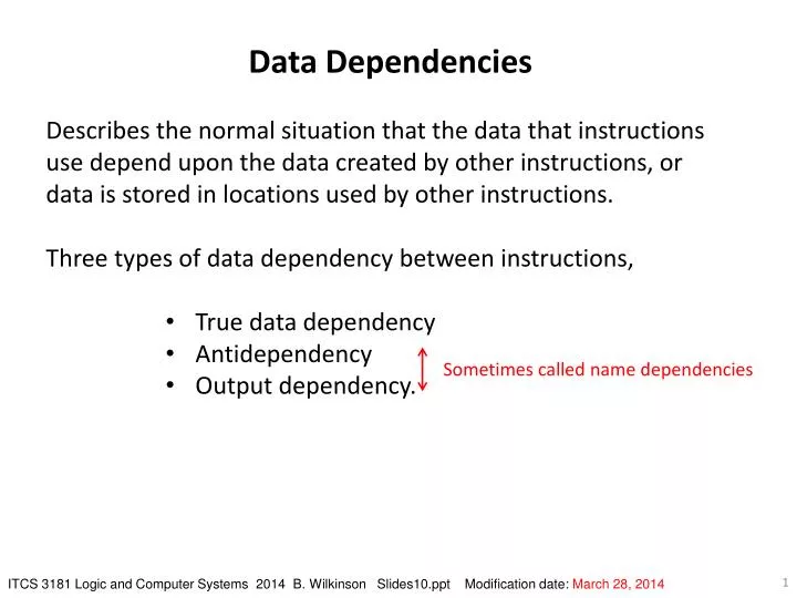
Data Dependencies Describes the normal situation that the data that instructions use depend upon the data created by other instructions, or data is stored in locations used by other instructions. Three types of data dependency between instructions, True data dependency Antidependency

E N D
Data Dependencies • Describes the normal situation that the data that instructions use depend upon the data created by other instructions, or data is stored in locations used by other instructions. • Three types of data dependency between instructions, • True data dependency • Antidependency • Output dependency. Sometimes called name dependencies ITCS 3181 Logic and Computer Systems 2014 B. Wilkinson Slides10.ppt Modification date: March 28, 2014
True data dependency Occurs when value produced by an instruction is required by a subsequent instruction. Also known as flow dependencybecause dependency is due to flow of data in program Also called read-after-write hazardbecause reading a value after writing to it. Example 1. ADD R3,R2,R1 ;R3 = R2 + R1 2. SUB R4,R3,1 ;R4 = R3 - 1 “data” dependency between instruction 1 and 2 (R3). In general, they are the most troublesome to resolve in hardware.
Antidependency Occurs when an instruction writes to a location which has been read by a previous instruction. Also called an antidependency Also called a write-after-read hazard Example 1. ADD R3,R2,R1 ;R3 = R2 + R1 2. SUB R2,R5,1 ;R2 = R5 - 1 Instruction 2 must not produce its result in R2 before instruction 1 reads R2, otherwise instruction 1 would use the value produced by instruction 2 rather than the previous value of R2.
Antidependencies in a single pipeline In most pipelines, reading occurs in a stage before writing and an antidependency would not be a problem. Becomes a problem if the pipeline structure is such that writing can occur before reading in the pipeline, or the instructions are not processed in program order - see later.
Output dependency Occurs when a location is written to by two instructions. Also called write-after-write hazard. Example 1. ADD R3,R2,R1 ;R3 = R2 + R1 2. SUB R2,R3,1 ;R2 = R3 - 1 3. ADD R3,R2,R5 ;R3 = R2 + R5 Instruction 1 must produce its result in R3 before instruction 3 produces its result in R3 otherwise instruction 2 might use the wrong value of R3.
Output dependencies in a single pipeline Again dependency not significant in a single pipeline if all instructions write at the same time in the pipeline and instructions are processed in program order. Output dependencies are a form of resource conflict, because the register in question is accessed by two instructions. The register is being reused. Consequently, the use of another register in the instruction would eliminate the potential problem.
Detecting hazards Can be detected by considering read and write operations on specific locations accessible by the instructions: A read-after-write hazard exists if read operation occurs before previous write operation has been completed, and hence read operation would obtain incorrect value (a value not yet updated). A write-after-readhazard exists when write operation occurs before previous read operation has had time to complete, and again the read operation would obtain an incorrect value (a prematurely updated value). A write-after-write hazard exists if there are two write operations upon a location such that the second write operation in the pipeline completes before the first. Read-after-read hazards, in which read operations occur out of order, do not normally cause incorrect results.
Mathematical Conditions for Hazard (Berstein’sConditions) Let: O(i) indicate the set of (output) locations altered by instruction i; I(i) indicate the set of (input) locations read by instruction i, ɸindicates an empty set. A potential hazard exists between instruction i and a subsequent instruction j when at least one of the following conditions fails: For read-after-write O(i) I(j) = ɸ For write-after-read I(i) O(j) = ɸ For write-after-write O(i) O(j) = ɸ Null sets, i.e. left sides are disjoint sets
If not disjoint sets Between instruction i and instruction j (after it) In this example only
Example Suppose we have code sequence: 1. ADD R3,R2,R1 ;R3 = R2 + R1 2. SUB R5,R1,1 ;R5 = R1 - 1 entering the pipeline. We have: O(1) = (R3) O(2) = (R5) I(1) = (R1,R2) I(2) = (R1) The conditions: (R3) (R1) = ɸ (R2,R1) (R5) = ɸ (R3) (R5) = ɸ are satisfied and there are no hazards
Berstein’s Conditions can be extended to cover more than two instructions. Number of hazard conditions to be checked becomes quite large for a long pipeline having many partially completed instructions. Satisfying conditions are sufficient but not necessary in mathematical sense. May be that in a particular pipeline a hazard does not cause a problem.
Direct hardware method of checking Berstein’s conditions Do logical comparisons between the source and destination register identification number of pairs of instructions in pipeline. Checking hazards between two instructions in pipeline
Although previous method can be extended to any number of instructions, it is complex and a much simpler method that is usually sufficient is as follows: Pipeline interlock using register valid bits Associate a 1-bit flag (valid bit) with each operand register. Flag indicates whether a valid result exists in register, say 0 for not valid and 1 for valid.
Resetting valid bit (invalid) A fetched instruction which will write to the register examines the valid bit. If the valid bit is 1, it is reset to 0 (if not already a 0*) to show that the value will be changed. * We shall show later that the instruction must stall if its destination register is already set invalid. Suppose instruction is ADD R3,R2,R2 Valid bit of R3 reset.
Setting bit (valid) Done during operand store stage. When the instruction has produced the value, it loads the register and sets the valid bit to 1, letting other instructions have access to the register.
Reading valid bit Done during the operand fetch stage. Any instruction which wants to read register operands has to wait until the registers valid bits have been set before reading the operands. Suppose subsequent instruction is SUB R4,R3,1. It stalls until ADD R3,R2,R1 stores its result and sets the valid bit:
Register read/write hazard detection using valid bits (IF, instruction fetch; RD, read operand; EX, execute phase; WR write operand)
Another Example Suppose the instruction sequence is: 1. ADD R3,R4,4 2. SUB R5,R3,8 3. SUB R6,R3,12 Read-after-write hazard between instr. 1 and instr. 2 (R3). Read-after-write hazard between instr. 1 and instr. 3 (again R3). In this case, sufficient to reset valid bit of R3 register to be altered during stage 2 of instr. 1 in preparation for setting it in stage 4. Both instructions 2 and 3 must examine valid bit of their source registers prior to reading contents of registers, and will hesitate if they cannot proceed.
Caution The valid bit approach has the potential of detecting all hazards, but write-after-write (output) hazards need special care.
Example Suppose the sequence is: 1. ADD R3,R4,R1 2. SUB R3,R4,R2 3. SUB R5,R3,R2 (very unlikely sequence, but poor compiler might create such redundant code). Instruction 1 will reset valid bit of R3 in preparation to altering its value. Instruction 2 will find valid bit already reset. If instruction 2 were to be allowed to continue, instruction 3 would only wait for the valid bit to be set, which would first occur when instruction 1 writes to R3. Instruction 3 would get value generated by instruction 1, rather than value generated by instruction 2 as called for in program sequence.
Correct algorithm for resetting valid bit WHILE destination register valid bit = 0 wait (pipeline stalls), else reset destination register valid bit to 0 and proceed.
Forwarding Refers to passing result of one instruction directly to another instruction to eliminate use of intermediate storage locations. Can be applied at compiler level to eliminate unnecessary references to memory locations by forwarding values through registers rather than through memory locations. Forwarding can also be applied at hardware level to eliminate pipeline cycles for reading registers updated in a previous pipeline stage. Eliminates register accesses by using faster data paths.
Internal forwarding Internal forwarding is hardware forwarding implemented by processor registers or data paths not visible to the programmer. Example ADD R3,R2,R0 SUB R4,R3,8 Subtract instruction requires contents of R3, which is generated by the add instruction. The instruction will be stalled in the operand fetch unit waiting for the value of R3 to be come valid. Internal forwarding forwards the value being stored in R3 by the operand store unit directly to the execute unit.
Internal forwarding in a five stage pipeline More details:
Forwarding using multiple functional units Concept of forwarding can be taken further by recognizing that instructions can execute as soon as the operands they require become available, and not before. Each instruction produces a result which needs to be forwarded to all subsequent instructions that are waiting for this particular result. This is seen in processors having multiple arithmetic/logic units (most current processors)