Download
1 / 29
300 likes | 1.16k Views
Learning Objectives. Use AutoCAD to draw an oblique of an object given orthographic views of the objectSelect the best orientation of an object in pictorialDefine what makes a drawing a: cavalier oblique, cabinet oblique, general oblique, isometric, axonometric, perspective, or orthographic viewsUse AutoCAD to generate Isometric Drawings of objects given the orthographic views of the object..

E N D
1. Pictorials with AutoCAD Class 8.2 : Using AutoCAD to Create Pictorial Drawings
2. Learning Objectives Use AutoCAD to draw an oblique of an object given orthographic views of the object
Select the best orientation of an object in pictorial
Define what makes a drawing a: cavalier oblique, cabinet oblique, general oblique, isometric, axonometric, perspective, or orthographic views
Use AutoCAD to generate Isometric Drawings of objects given the orthographic views of the object.
3. Types Obliques
Cavalier
Cabinet
General
Axonometrics
Isometrics
Dimetric, Trimetric
Perspectives
1,2,or 3 points
4. Cavalier Oblique Front view true size
Receding Axis Angle (Normally 30�, 45�
or 60�) is Variable
Depth dimension (receding axis) true size
5. Cabinet Oblique Front view true size
Receding Axis Angle (Normally 30�, 45� or 60�) is Variable
Depth dimension (receding axis) half size
6. General Oblique Front view true size
Receding Axis Angle (Normally 30�, 45� or 60�) is Variable
Depth dimension (receding axis) between half (D/2) and full size (D)
7. Angles in Oblique Angles in front view are drawn true size
Other angles must be located using coordinates
Appearance of angles may be distorted
8. Obliques Obliques are theoretical drawings. In reality, you can not actually view an object as an Oblique
Thin parts look very good as Obliques
Parts with angular features on multiple planes are difficult to draw as Obliques
9. Circles in Oblique Drawn true size in front view
Drawn as ellipses on receding planes
Layout using a Rhombus
10. Today�s AutoCAD commands Drawing setup
Drawing Aids
Display control
ZOOM
General Concepts
Keyboard Coordinates
Editing and inquiry
MOVE
COPY
TRIM
Review polar coordinates
used with copy and move:
Example: @1.2<45
Object Snap
ENDPoint
TANgent
NEArest
11. Display Control ZOOM -- scales the screen view to an area of the drawing surface
�Window� will zoom down to a window
�All� will zoom out to show the larger of the drawn entities or limits
Realtime allows you to shrink or enlarge the display in real time.
PAN -- moves around on the drawing surface
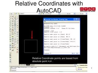
12. Formats of Keyboard Coordinates Either absolute or relative
Absolute -- references origin of drawing (0,0)
Relative -- references previously selected point
Absolute is the default
Precede relative coordinates with an @ sign
@10,20 or @ 10<45
Direct Distance
Enter a distance in the direction of the cursor and return
13. Grips Grips serve two purposes:
Basic editing of properties
Modification of size/location
Grips are the small hollow squares which appear when you select an object
If you click on a hollow square grip, it will become active and you can drag the grip to a new location. The actual effect of this will vary depending on what object and which grip you select.
14. Modifying Properties via Grips Once an object is selected and the grips are visible, you can change the Layer, Linetype, Color, and LineWeight by using the properties toolbar at the top of the screen.
Anytime you have an object activated with grips, the properties toolbar modify the object properties, not the drawing settings.
15. Drawing Obliques in AutoCAD Always make a rough pencil sketch of the object first to get an idea of what your drawing should look like.
Draw the front view as a flat orthographic view
Use the COPY command along with keyboard coordinates to place the front view along the receding axis to represent all frontal surfaces in the object
Connect the copies with lines representing the depth of the object. Remember to use OSNAP to assist in this process
Use ERASE and TRIM as appropriate to remove unwanted lines/arcs
16. Example
17. Example
18. Construction of an oblique Draw the front view using normal AutoCAD commands and techniques
19. Construction of an oblique Use the COPY command to replicate the front view to depict the depth
Command: COPYE
Select objects: [Other corner:[ 11 found
Select objects:E
<Base point or displacement>/Multiple: mE
Base point: [
Second point of displacement: @.8<40E
Second point of displacement: @1.8<40E
Second point of displacement:E
20. Construction of an oblique ERASE the portions of the depth profiles which will not be seen.
Command: eraseE
Select objects:[
Select objects:[
�
Select objects: [
Select objects: E
21. Construction of an oblique Add receding lines using OSNAP and the LINE command.
Command: lineE
From Point: endpE of[
To Point: endpE of[
To Point:E
�
22. Construction of an oblique TRIM and ERASE the remaining lines which would not be visible.
Command: TRIME
Select cutting edges: (Projmode = UCS, Edgemode = No extend)
Select objects: [1 found
Select objects:E
<Select object to Trim>/Project/Edge/Undo:[
<Select object to trim>/Project/Edge/Undo:E
23. Exercise 8.2.1: Cavalier Oblique.
24. Isometrics Axes equally separated (120�)
H, W, and D measurements are true size along iso. axes
Angles must be located by coordinates
Circles appear as ellipses on all surfaces
25. Drawing Isometrics in AutoCAD Initially you should do a rough sketch of the object by hand to get an idea of what your drawing should look like
Switch the crosshairs to isometric mode (snap, style, iso)
Draw the object using the LINE and ELLIPSE commands
Use F5 to toggle the current isometric plane
Use OTRHO and OSNAP to assist you in the drawing
Copy face planes along isometric axes and connect corners similar to oblique method shown earlier
TRIM or ERASE any portions which are not visible
26. Using isometric snap If the crosshairs are not set in isometric mode, use the Drafting Settings dialog box.
Right click on snap button and choose settings
27. Drawing Ellipses In isometrics, circular features which lie on the principal planes are shown as ellipses
These MUST be drawn using the ELLIPSE command with the Isocircle option
28. Individual Exercise; Draw an Isometric pictorial of the object shown on the next slide using AutoCAD.
The grid is a .2� grid
Use template English1.dwt
29. Isometric Example
30. Individual Assignment 41 B&C: Cabinet oblique
43 B&C: Cavalier oblique
48 C&D: isometric
49 C&D: isometric
Due: Thursday 28 October 2004