Download
1 / 186
1.95k likes | 2.18k Views
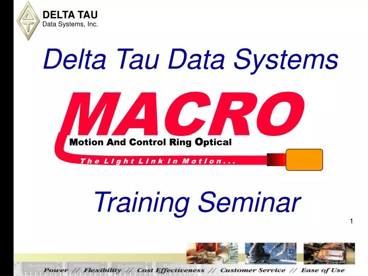
Delta Tau Data Systems. MACRO. M otion A nd C ontrol R ing O ptical. T h e L I g h t L I n k I n M o t I o n. Training Seminar. Introduction. M otion A nd C ontrol R ing O ptical

E N D
Delta Tau Data Systems MACRO Motion And Control Ring Optical T h e L I g h t L I n k I n M o t I o n . . . Training Seminar
Introduction Motion And Control Ring Optical MACRO is a high speed bus interface for connection of multi-axis motion controllers, amplifiers, and I/O on a fiber optic or twisted pair copper (RJ45 connector) ring.
MACRO Applications MACRO lends itself to large multi-axis applications where the amplifiers and I/O are spread out as well as smaller applications where wiring simplicity and noise immunity are preferred. Packaging Automatic welding Converting Material handling Silicon wafer processing Machine tools Textiles machinery Food processing Robotics Automated assembly lines
MACRO Course Overview • MACRO Transmission Overview • MACRO Hardware Overview • MACRO Nodes Defined • MACRO Communications Setup • MACRO Commands • Motor Setup (Using Servo Nodes) • IO Setup (Using IO Nodes) • Trouble Shooting Techniques • Hands-On hardware setup
MACRO NETWORK TRANSMISSION Network Interface Driver IC Network Interface Driver IC Byte- wide Shift Registers Byte- wide Shift Registers 125 MHz Optical Driver Optical Driver 125 MHz Local CPU Local CPU Electrical Driver Electrical Driver 10 MHz 10 MHz
Standard PMAC / MACRO Comparison STANDARD PMAC CONCEPT DIRECT PWM DIG. CURRENT RAM PWM +/- 10 V. DAC Output DAC CPU ROM A ENCODER B Feedback ENC COUNTERS FLASH Machine I/0 Connector MACRO CONCEPT (MACRO IS TRANPARENT) PMAC and MACRO Interface MACRO STATION / DRIVES ENCODER A/B QUAD ENC TAXI TAXI RAM PWM PWM CPU CPU ROM MACRO MACRO DAC +/- 10 V. TAXI TAXI FLASH 96 I/O I/O NO RAM OR FLASH
MACRO Transmission Media • Glass fiber with SC connectors • Up to 3000m (10,000 ft) between stations • Total EMI immunity in transmission • Ordered with Option A on PMAC or MACRO Station • RJ-45 electrical connection • Up to 30m (100 ft) between stations • Transformer isolation at both ends • Less expensive for shorter distances • Ordered with Option C on PMAC or MACRO Station
MACRO Advantages • Very long distances between nodes possible • Up to 3000m (10,000ft) with optical fiber • Up to 30m (100 ft) with RJ-45 electrical • Optical transmission for complete noise immunity • Isolated electrical transmission possible • Eliminates potential ground-loop problems • Very high raw data rate (125 Mbps) • Very simple ring data timing control • Master/slave scheme • Multi-master control with baton passing • No overhead for collision prevention/detection • Result is very high effective data rate
MACRO Advantages • All actual data transfers are synchronous • Very simple structure for cyclic servo data • Asynchronous data can stay on ring for multiple cycles • Ability to close all loops across the ring • Position and velocity loops • Commutation and current loop (unique!) • Very simple ring data protocol • Simple copying of servo commands and feedback • Simple copying of I/O values • On-the-fly substitution of feedback into data stream • No worry about collisions • Eliminates 1 ring-cycle delay, permitting higher gains
MACRO Ring Master/Slave Concepts • Master/slave protocol is simpler, more deterministic than peer-to-peer • Generally, PMACs are masters on the ring • MACRO Devices are slaves on the rings • Multiple masters supported on a single ring, coordinated thru “baton” passing (simpler than token passing)
MACRO Ring Master/Slave Operation • Ring Master: On phase clock, sends data packet for each active node, then sends “baton”. One and only one ring master must be present on ring. • Master: On receipt of baton, sends data packet for each active node, then sends baton. • Slave: Latches in data packet received for any node; substitutes feedback packet for active node, retransmits packet for inactive node (permitting broadcast).
MACRO Real-Time Transmission • Dedicated use of MACRO nodes for cyclic data transmission • Used for servo commands and feedback • Used for fast I/O • Data can be exchanged (up to) every phase cycle • Standard protocols for exchange of data
Delta Tau MACRO Master Controllers • Turbo Ultralites (PCI, VME) • PowerPMAC Ultralite • UMAC Turbo PMAC2 with ACC-5E • UMAC PowerPMAC with ACC-5E/ACC-5E3 • BRICK Family with MACRO interface
MACRO Slave Devices • MACRO CPU (legacy) • MACRO16 CPU • MACRO Peripheral Devices • MACRO Amplifiers & 3rd Party Products
MACRO 8-Axis CPU • One MACRO IC • 8 MACRO servo nodes • 6 MACRO I/O nodes • 2 MACRO auxiliary communications nodes • Serial Port • Multiplexor Port • LED Display • Two Hardware Switches
MACRO 16-Axis CPU • Two MACRO IC’s • 16 MACRO servo nodes • 12 MACRO I/O nodes • 4 MACRO auxiliary communications nodes • Compiled PLC’s • Serial Port • Handwheel Port • Display Port • LED Display and Two hardware switches
MACRO Peripherals • Standalone MACRO Devices • Analog and Digital IO Cards • 2 axis Servo and 4 axis Stepper • USB Port for Direct communications and firmware download • MACRO Display Port • DAC/ADC/AENA Port Option
Jumpers ALL Products MACRO Peripheral * E40 on MACRO CPU (602802-10x)
MACRO Display • The MACRO Station has a single hexadecimal display on the CPU/Interface Board. The display can show the following values • {blank}Ring not active • 0-8Operation OK. Value is number of active motors • 9(reserved for future use) • AAmplifier Fault • BRing Break Fault • CCPU Failure Fault • DRing Data Error • ELoss-of-encoder Fault • FOther Failure
GEO MACRO • Up to 2 Servo Drives • 2 encoder • 2 Flag Sets (PLIM, MLIM, USER, HMFL) • USB Port for Direct communications and firmware download • MACRO LED Display • 12-bit ADC Port Option • 4 inputs and 4 outputs
MACRO Amplifiers • Delta Tau GEO MACRO Drives • Copley • Etel • Moog • ABB • Yaskawa • Kollmorgen
MACRO Station Configurations • “UMAC MACRO System” • 3U boards • UMAC backplane connections • Boards/modules slide in and out • Mounted in enclosed 3U Euro-rack • Labeled connectors and indicators • “MACRO-Stack” (obsolete) • 3U boards with inter-board “stack” connectors • Can be mounted with standoffs • Can be mounted in 3U Euro-rack
UMAC MACRO Advantages • Modular • Extremely Compact • MACRO-Pack Designed Boards Plug into Expansion Bus • CE Compliant
UMAC Axis and Feedback Boards • MACRO Interface/CPU Board • ACC-24E2 Digital PWM 2/4-Axis Interface/Breakout • ACC-24E2A Analog ±10V 2/4-Axis Interface/Breakout • ACC-24E2S 4-Axis Stepper Axis Interface Board • ACC-28E High Resolution 16-bit A/D Converter • ACC-51E 4096 Interpolator • ACC-53E SSI Encoder Interface • ACC-57E Yaskawa or Mitsubishi Encoder Interface • ACC-70E Tamagawa Absolute Encoder Interface
UMAC MACRO I/O Boards • ACC-11E Isolated 24-In/24-Out (24V, 100mA) Board • ACC-14E 48-I/O Board (5V) • ACC-28E 4 Channels 16-bit ADC • ACC-36E 16 channels 12-bit ADC • ACC-59E 8 12-bit ADC and 8 12-bit DAC Channels • ACC-65E Self-protected 24-In/24-Out (24V, 250mA) Board • ACC-66E Self-protected 48-In (24V, 250mA) Board • ACC-67E Self-protected 48-Out (250mA) Board • ACC-68E Self protected 24-In/24-Out Sinking
MACRO Developers Kit • Description of How MACRO Works • Discussions of MACRO Use • Examples of MACRO Implementations • MACRO Specification • Component Data Sheets
PMAC/MACRO Station Communication The MACRO ring operates by copying registers at high speed across the ring. Therefore, the each master controller (TPMAC, PPMAC) on the ring communicates with its slave stations by reading from and writing to registers in its own address space. MACRO hardware automatically handles the data transfers across the ring.
Node Transfer Concepts • Each PMAC MACRO IC has 16 nodes • Each MACRO Station CPU can have up to 16 activated nodes. • New MACRO16 can have up to 32 activated nodes (two MACRO IC’s) • Information is passed from the activated nodes at the MACRO Station and PMAC .
Ring Update Frequency Considerations • 1.6 µsec per active master node required • Update must be as fast as loop closure rate • Current loops usually closed at 8-10 kHz • Position loops usually closed at 1-4 kHz • Nice to have 2 ring updates per 1 loop update • 32 nodes permits 20 kHz ring update • 64 active nodes permits 10 kHz ring update • 256 active nodes permits 2.5 kHz ring update
MACRO Node Activation Control The MACRO Station MACRO IC has Nodes which can be activated to perform servo loop closure operations or transfer data for input/output operations. Axis Nodes NODE 15 14 13 12 11 10 9 8 7 6 5 4 3 2 1 0 I/O Nodes I/O or Master/Master Always Set to 1 for Type 1 Protocol
PMAC/MACRO Station Register Mapping Motor x Calculation Registers MACRO Station Machine Interface Channel x Registers Channel Interface Signals Servo & Commutation Address I-variables Station SW1 Setting, Conversion Table, MI10x PMAC MACRO Node n Registers MACRO Station Node n Registers TPMAC: I6840,I6890,I6940,I6990…… PPMAC: Gate2[i].MacroMode, Gate2[i].MacroEnable PMAC Node n = Station Node n MACRO Station PMAC
Flag Holding registers 0 1 2 3 PMAC Node n Registers Motor x Calculation Registers 0 1 2 3 Encoder Conversion Table TPMAC Servo and Commutation Addressing Ix25 Flag Registers I70-I77 Ix02 Command Output Command Registers MACRO OUT Feedback Registers MACRO IN Ix83 Commutation Feedback Ix84 Current Feedback Ix03, Ix04 Servo position Feedback Table Entry I8000…
Flag Holding registers Automatic 0 1 2 3 PMAC Node n Registers Motor x Calculation Registers 0 1 2 3 Encoder Conversion Table PPMAC Servo and Commutation Addressing Motor[x].pAmpFault, Motor[x].pLimits … Flag Registers feedback Motor[1].pAmpEnable … Flag Registers command Motor[x].pDac Command Output Command Registers MACRO OUT Feedback Registers MACRO IN Motor[x].pPhaseEnc Commutation Feedback Motor[x].pAdc Current Feedback Table Entry Motor[x].pEnc Motor[x].pEnc2 Servo position Feedback EncTable[x].pEnc
0 1 2 3 Station Node n Registers 0 1 2 3 0 1 2 3 PMAC Node n Registers 0 1 2 3 PMAC/MACRO Station Node Matching MACRO hardware automatically copies every phase cycle Command (output) Registers Command (input) registers Feedback (input) Registers Feedback (output) Registers PMAC Node Master Number set by I6840 bits (20-23) in TPMAC Gate2[i].MacroMode bits (20-23) in PPMAC Station Node Master Number set by SW2 Node Slave Number n automatically matches between PMAC and MACRO Station
0 1 2 3 Station Node n Registers 0 1 2 3 MACRO Station Node-to-Channel Mapping Machine Interface Channel x Registers Node n to Channel x mapping is determined by station SW1 setting DAC, PWM Output A DAC, PWM Output B PWM Output C AMP Enable Control MACRO IN MACRO OUT Flags Status Current Feedback Signals ADC B ADC A Station Encoder Conversion Table MI120-MI151 Position Feedback Signal Encoder MI10x
TPMAC/PPMAC Memory Mapping TPMAC: Motor setup: I102=$78420 IO Setup: m960->x:$78420,0,24 m963->x:$78423,8,16 PPMAC: Motor setup: Motor[1].pDac = Gate2[0].Macro[0][0].a IO Setup: MyFirstReg->Gate2[0].Macro[2][0] MyThirdReg->Gate2[0].Macro[2][3] Gate2[i].Macro[m][n] IO address is Base_address + m*16 + n*4 + $100 Gate2[0].Macro[2][0] is $800000 + 32($20) + 0 + $100 Gate2[0].Macro[2][3] is $800000 + 32($20) + 12($C) + $100 MyFirstReg->u.io.$800120.8.24 MyThirdReg->u.io.$80012C.16.16
MACRO Communications Setup • Determine Your Ring Frequency • Default of 9 kHz • Based on Phase Clock and Servo Clock Needs • Determine how many nodes your application is using • Setup Communications at PMAC • Setup Communications at MACRO CPU • Switch Settings or Ring Order Method
MACRO RING CLOCK SETUP It is important for the MACRO user to set the ring cycle frequencies of the synchronizing master, non-synchronizing masters and slaves equal to each other for proper MACRO data transfers. • Using one of the Delta Tau setup programs then the clocks will always be setup properly. • The factory default settings for the ring cycle are identical at both the PMAC and the MACRO Station. If the user is using factory default settings for the ring frequency then they will not have to worry about the system ring clock settings.
Ring Update Frequency Control • Ring updated at phase-clock frequency of ring master • Other master and slave stations kept sync’ed • These should be set to same frequency for best performance
Phase Clock Frequency Control • Frequency set by two variables • First variable sets “MaxPhase” frequency • Second variable divides MaxPhase to Phase • Turbo PMAC: I6800 & I6801 • Power PMAC: Gate2[i].PwmPeriod & Gate2[i].PhaseClockDiv • MACRO Station: MI992 & MI997
Turbo PMAC“MaxPhase” Frequency Control • MaxPhase (kHz) = 117,964.8 / [2*I6800+3] • I6800 = (117,964.8 / [2*MaxPhase(kHz)]) – 1 • MACRO Station : MI992 • PWM frequency for Station channels 1 - 8 (ACC-24E2) must be set to • N * MaxPhase / 2 I6800 = 6527 Default Value