Download
1 / 69
690 likes | 692 Views
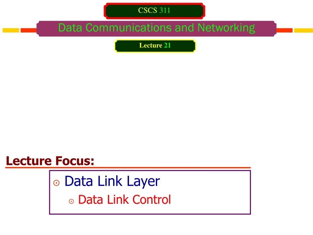
Lecture Focus:. Data Link Layer Data Link Control. CSCS 311. Data Communications and Networking. Lecture 21. Data Link Control. Two main functions of the data link layer: Data Link Control Media Access Control

E N D
Lecture Focus: Data Link Layer Data Link Control CSCS 311 Data Communications and Networking Lecture 21
Data Link Control • Two main functions of the data link layer: • Data Link Control • Media Access Control • The data link control deals with the design and procedures for communication between two adjacent nodes: node-to-node communication. • Data link control functions: • Framing • Flow control • Error control • Software implemented protocols that provide smooth and reliable transmission of frames between nodes
Data Link Control • Framing deals with how to organize the bits that are carried by the physical layer. • Flow control refers to a set of procedures used to restrict the amount of data that the sender can send before waiting for acknowledgment. • To implement data link control, we need protocols. • Each protocol is a set of rules that need to be implemented in software and run by the two nodes involved in data exchange at the data link layer. • We will discuss five protocols: • Two for noiseless (ideal) channels • Three for noisy (real) channels
Data Link Control Framing • The data link layer packs bits into frames, so that each frame is distinguishable from another. • Our postal system practices a type of framing. • Simple act of inserting a letter into an envelope separates one piece of information from another; the envelope serves as the delimiter. • In addition, each envelope defines the sender and receiver addresses since the postal system is a many-to-many carrier facility. • Framing in the data link layer separates a message from one source to a destination, or from other messages to other destinations, by adding a sender address and a destination address. • Destination address defines where the packet is to go. • Sender address helps the recipient acknowledge the receipt.
Data Link Control Framing • Although the whole message could be packed in one frame, that is not normally done. • One reason is that a frame can be very large, making flow and error control very inefficient. • When a message is carried in one very large frame, even a single-bit error would require the retransmission of the whole message. • When a message is divided into smaller frames, a single-bit error affects only that small frame.
Data Link Control Framing Types of Framing Fixed-Size Framing • In fixed-size framing, there is no need for defining the boundaries of the frames; the size itself can be used as a delimiter. Variable-Size Framing • Prevalent in local area networks • In variable-size framing, we need a way to define the end of the frame and the beginning of the next. • Historically, two approaches were used for this purpose: • Character-oriented approach • Bit-oriented approach
Data Link Control Framing Types of Framing Variable-Size Framing : Character-oriented approach • Data to be carried are 8-bit characters from a coding system such as ASCII. • The header normally carries the source and destination addresses and other control information, and • The trailer carries error detection or error correction redundant bits • Both header and trailer are also multiples of 8 bits. • To separate one frame from the next, an 8-bit (1 byte) flag is added at the beginning and the end of a frame. • The flag, composed of special characters, signals the start or end of a frame.
Data Link Control Framing Types of Framing Variable-Size Framing : Character-oriented approach • Figure below shows the format of a frame in a character-oriented protocol. Data from upper layer Variable number of characters Flag Header Trailer Flag
Data Link Control Framing Types of Framing Variable-Size Framing : Character-oriented approach • Character-oriented framing was popular when only text was exchanged by the data link layers. The flag could be selected to be any character not used for text communication. • Now, we send other types of information such as graphs, audio, and video. • Any pattern used for the flag could also be part of the information. • If thishappens, the receiver, when it encounters this pattern in the middle of the data, thinks it has reached the end of the frame.
Data Link Control Framing Types of Framing Variable-Size Framing : Character-oriented approach Byte-stuffing: • To fix this problem, a byte-stuffing strategy was added to character-oriented framing. • In byte stuffing (or character stuffing), a special byte is added to the data section of the frame when there is a character with the same pattern as the flag. • The data section is stuffed with an extra byte. • This byte is usually called the escape character (ESC), which has a predefined bit pattern. • Whenever the receiver encounters the ESC character, it removes it from the data section and treats the next character as data, not a delimiting flag. In byte stuffing, we add 1 extra byte whenever there is a flag or escape character in the text.
Data Link Control Framing Types of Framing Variable-Size Framing : Character-oriented approach Byte-stuffing: • Byte stuffing by the escape character allows the presence of the flag in the data section of the frame, but it creates another problem. • What happens if the text contains one or more escape characters followed by a flag? The receiver removes the escape character, but keeps the flag, which is incorrectly interpreted as the end of the frame. • To solve this problem, the escape characters that are part of the text must also be marked by another escape character. In other words, if the escape character is part of the text, an extra one is added to show that the second one is part of the text.
Data Link Control Framing Types of Framing Variable-Size Framing : Character-oriented approach Byte stuffing and un-stuffing Byte-stuffing:
Data Link Control Framing Types of Framing Variable-Size Framing : Character-oriented approach • Character-oriented protocols present another problem in data communications. • The universal coding systems in use today, such as Unicode, have 16-bit and 32-bit characters that conflict with 8-bit characters. • The tendency is moving toward the bit-oriented protocols.
Data Link Control Framing Types of Framing Variable-Size Framing : Bit-oriented approach • The data section of a frame is a sequence of bits to be interpreted by the upper layer as text, graphic, audio, video, and so on. • However, in addition to headers (and possible trailers), we still need a delimiter to separate one frame from the other. • Most protocols use a special 8-bit pattern flag 01111110 as the delimiter to define the beginning and the end of the frame.
Data Link Control Framing Types of Framing Variable-Size Framing : Bit-oriented approach Data from upper layer Variable number of bits 01111110 Header 0101010111010101001…….10101111111001010 Trailer 01111110 Flag Flag
Data Link Control Framing Types of Framing Variable-Size Framing : Bit-oriented approach Bit-Stuffing • This flag can create the same type of problem we saw in the byte-oriented protocols. That is, if the flag pattern appears in the data, we need to somehow inform the receiver that this is not the end of the frame. • We do this by stuffing 1 single bit (instead of 1 byte) to prevent the pattern from looking like a flag. • In bit stuffing, if a 0 and five consecutive 1 bits are encountered, an extra 0 is added. • This extra stuffed bit is eventually removed from the data by the receiver. • Note that the extra bit is added after one 0 followed by five 1s regardless of the value of the next bit. • This guarantees that the flag field sequence does not inadvertently appear in the frame.
Data Link Control Framing Types of Framing Variable-Size Framing : Bit-oriented approach Bit-Stuffing Bit stuffing is the process of adding one extra 0 whenever five consecutive 1s follow a 0 in the data, so that the receiver does not mistake the pattern 0111110 for a flag.
Data Link Control Framing Types of Framing Variable-Size Framing : Bit-oriented approach Bit-Stuffing Bit stuffing and un-stuffing
Data Link Control Framing Types of Framing Variable-Size Framing : Bit-oriented approach Bit-Stuffing If the flag like pattern 01111110 appears in the data, it will change to 011111010 (stuffed) and is not mistaken as a flag by the receiver. The real flag 01111110 is not stuffed by the sender and is recognized by the receiver.
Data Link Control FLOW AND ERROR CONTROL • Data communication requires at least two devices working together, one to send and the other to receive. • Even such a basic arrangement requires a great deal of coordination for an intelligible exchange to occur. • The most important responsibilities of the data link layer are flow control and error control. • Collectively, these functions are known as data link control.
Data Link Control FLOW AND ERROR CONTROL Flow Control • Flow control coordinates the amount of data that can be sent before receiving an acknowledgment and is one of the most important duties of the data link layer. • In most protocols, flow control is a set of procedures that tells the sender how much data it can transmit before it must wait for an acknowledgment from the receiver. • The flow of data must not be allowed to overwhelm the receiver. • Any receiving device has a limited speed at which it can process incoming data and a limited amount of memory in which to store incoming data.
Data Link Control FLOW AND ERROR CONTROL Flow Control • The receiving device must be able to inform the sending device before those limits are reached and to request that the transmitting device send fewer frames or stop temporarily. • Incoming data must be checked and processed before they can be used. • The rate of such processing is often slower than the rate of transmission. • For this reason, each receiving device has a block of memory, called a buffer, reserved for storing incoming data until they are processed. • If the buffer begins to fill up, the receiver must be able to tell the sender to halt transmission until it is once again able to receive. • Flow control refers to a set of procedures used to restrict the amount of data that the sender can send before waiting for acknowledgment.
Data Link Control FLOW AND ERROR CONTROL Error Control • Error control is both error detection and error correction. • It allows the receiver to inform the sender of any frames lost or damaged in transmission and coordinates the retransmission of those frames by the sender. • In the data link layer, the term error control refers primarily to methods of error detection and retransmission. • Error control in the data link layer is often implemented simply: Any time an error is detected in an exchange, specified frames are retransmitted. • This process is called automatic repeat request (ARQ).
Data Link Control PROTOCOLS • Data link layer combines framing, flow control, and error control to achieve the delivery of data from one node to another. • The protocols are normally implemented in software by using one of the common programming languages. • Types of protocols: • Protocols used for noiseless (error-free) channels • Protocols used for noisy (error-creating) channels • The protocols in the first category cannot be used in real life, but they serve as a basis for understanding the protocols of noisy channels.
Data Link Control PROTOCOLS PROTOCOLS For Noisy Channel For Noiseless Channel Stop-and-Wait ARQ Simplest Go-Back-N ARQ Stop-and-Wait Selective Repeat ARQ
Data Link Control PROTOCOLS • All the protocols we discuss are unidirectional in the sense that the data frames travel from one node, called the sender, to another node, called the receiver. • Although special frames, called acknowledgment (ACK) and negative acknowledgment (NAK) can flow in the opposite direction for flow and error control purposes, data flow in only one direction. • In a real-life network, the data link protocols are implemented as bi-directional; data flow in both directions.
Data Link Control PROTOCOLS NOISELESS CHANNELS • Noiseless channel is an ideal channel in which no frames are lost, duplicated, or corrupted. • Two protocols: • The first protocol does not use flow control • The second uses flow control • Of course, neither has error control because the channel is a perfect noiseless channel. Noiseless Channel Protocol Simplest Stop-and-Wait
Data Link Control PROTOCOLS : NOISELESS CHANNELS Simplest Protocol: • Simplest Protocol has no flow or error control. • We assume that the receiver can immediately handle any frame it receives with a processing time that is small enough to be negligible. • The data link layer of the receiver immediately removes the header from the frame and hands the data packet to its network layer, which can also accept the packet immediately. • The receiver can never be overwhelmed with incoming frames.
Data Link Control PROTOCOLS : NOISELESS CHANNELS Simplest Protocol: Procedure used by both data link layers: • The sender site cannot send a frame until its network layer has a data packet to send. • The receiver site cannot deliver a data packet to its network layer until a frame arrives. • If the protocol is implemented as a procedure, we need to introduce the idea of events in the protocol.
Data Link Control PROTOCOLS : NOISELESS CHANNELS Simplest Protocol: Procedure used by both data link layers: • The procedure at the sender site is constantly running; there is no action until there is a request from the network layer. • The procedure at the receiver site is also constantly running, but there is no action until notification from the physical layer arrives. • Both procedures are constantly running because they do not know when the corresponding events will occur.
Data Link Control PROTOCOLS : NOISELESS CHANNELS Algorithms Simplest Protocol: Sender-site algorithm for the simplest protocol while (true) //Repeat forever { WaitForEvent( ) //Sleep until an eventoccurs if( Event( RequestToSend ) ) // There is a packet to send { GetData( ); MakeFrame( ); SendFrame( ); // Send the frame } } 1 2 3 4 5 6 7 8 9 10
Data Link Control PROTOCOLS : NOISELESS CHANNELS Algorithms Simplest Protocol: Analysis: • The algorithm has an infinite loop, which means lines 3 to 9 are repeated forever once the program starts. • The algorithm is an event-driven one, which means that it sleeps (line 3) until an event wakes it up (line 4). • This means that there may be an undefined span of time between the execution of line 3 and line 4; there is a gap between these actions. • When the event, a request from the network layer, occurs, lines 6 though 8 are executed. • The program then repeats the loop and again sleeps at line 3 until the next occurrence of the event.
Data Link Control PROTOCOLS : NOISELESS CHANNELS Algorithms Simplest Protocol: Analysis: • GetData( ) takes a data packet from the network layer. • MakeFrame( ) adds a header and delimiter flags to the data packet to make a frame. • SendFrame( ) delivers the frame to the physical layer for transmission.
Data Link Control PROTOCOLS : NOISELESS CHANNELS Algorithms Simplest Protocol: Receiver-site algorithm for the simplest protocol while (true) //Repeat forever { WaitForEvent( ) //Sleep until an eventoccurs if( Event( ArrivalNotification ) ) // Data frame arrived { ReceiveFrame( ); ExtractData( ); DeliverData( ); // Deliver data to network layer } } 1 2 3 4 5 6 7 8 9 10
Data Link Control PROTOCOLS : NOISELESS CHANNELS Algorithms Simplest Protocol: Analysis: • The event here is the arrival of a data frame. • After the event occurs, the data link layer receives the frame from the physical layer using the ReceiveFrame( ) process, extracts the data from the frame using the ExtractData( ) process, and delivers the data to the network layer using the DeliverData( ) process. • We have an event-driven algorithm because the algorithm never knows when the data frame will arrive.
Data Link Control PROTOCOLS : NOISELESS CHANNELS Algorithms Simplest Protocol: Flow diagram
Data Link Control PROTOCOLS : NOISELESS CHANNELS Simplest Protocol: Algorithms • Above figure shows an example of communication using this protocol. • The sender sends a sequence of frames without even thinking about the receiver. • To send three frames, three events occur at the sender site and three events at the receiver site. • Note that the data frames are shown by tilted boxes; the height of the box defines the transmission time difference between the first bit and the last bit in the frame.
Data Link Control PROTOCOLS : NOISELESS CHANNELS Stop-and-Wait Protocol • If data frames arrive at the receiver site faster than they can be processed, the frames must be stored until their use. • Normally, the receiver does not have enough storage space, especially if it is receiving data from many sources. • This may result in either the discarding of frames or denial of service. • To prevent the receiver from becoming overwhelmed with frames, we somehow need to tell the sender to slow down. • There must be feedback from the receiver to the sender.
Data Link Control PROTOCOLS : NOISELESS CHANNELS Stop-and-Wait Protocol • In Stop-and-Wait Protocol, the sender sends one frame, stops until it receives confirmation from the receiver (okay to go ahead), and then sends the next frame. • We have unidirectional communication for data frames, but auxiliary ACK frames (simple tokens of acknowledgment) travel from the other direction. • We add flow control to our previous protocol. • We can see the traffic on the forward channel (from sender to receiver) and the reverse channel. • At any time, there is either one data frame on the forward channel or one ACK frame on the reverse channel. We therefore need a half-duplex link.
Data Link Control PROTOCOLS : NOISELESS CHANNELS Stop-and-Wait Protocol Algorithms Sender-site algorithm
Data Link Control PROTOCOLS : NOISELESS CHANNELS Algorithms Stop-and-Wait Protocol Sender-site algorithm Analysis: • Here two events can occur: • A request from the network layer or • An arrival notification from the physical layer • The responses to these events must alternate. • After a frame is sent, the algorithm must ignore another network layer request until that frame is acknowledged. • We know that two arrival events cannot happen one after another because the channel is error-free and does not duplicate the frames.
Data Link Control PROTOCOLS : NOISELESS CHANNELS Algorithms Stop-and-Wait Protocol Sender-site algorithm Analysis: • The requests from the network layer, however, may happen one after another without an arrival event in between. • We need somehow to prevent the immediate sending of the data frame. • Although there are several methods, we have used a simple canSend variable that can either be true or false. • When a frame is sent, the variable is set to false to indicate that a new network request cannot be sent until canSend is true. • When an ACK is received, canSend is set to true to allow the sending of the next frame.
Data Link Control PROTOCOLS : NOISELESS CHANNELS Algorithms Stop-and-Wait Protocol Receiver-site algorithm
Data Link Control PROTOCOLS : NOISELESS CHANNELS Algorithms Stop-and-Wait Protocol Receiver-site algorithm Analysis: • After the data frame arrives, the receiver sends an ACK frame (line 9) to acknowledge the receipt and allows the sender to send the next frame.
Data Link Control PROTOCOLS : NOISELESS CHANNELS Algorithms Stop-and-Wait Protocol ACK ACK
Data Link Control PROTOCOLS : NOISELESS CHANNELS Algorithms Stop-and-Wait Protocol • Above figure shows that the sender sends one frame and waits for feedback from the receiver. • When the ACK arrives, the sender sends the next frame.
Data Link Control PROTOCOLS NOISY CHANNELS • Simplest Protocol (Noiseless channel) has no flow or error control. • Stop-and-Wait Protocol (Noiseless channel) gives an idea of how to add flow control to Simplest Protocol. • Both of these protocols do not have a mechanism to control error. • Noiseless channels are nonexistent. • We can ignore the error, or • We need to add error control to our protocols. • Noisy Protocols use error control. What will be the effect?
Data Link Control PROTOCOLS NOISY CHANNELS Noisy Channel Protocols Stop-and-Wait ARQ* Go-Back-N ARQ Selective Repeat ARQ ARQ* = Automatic Repeat Request
Data Link Control PROTOCOLS: NOISY CHANNELS Stop-and-WaitARQProtocol • This protocol adds a simple error control mechanism to the Stop-and-Wait Protocol of Noiseless channel. • This protocol detects and corrects errors. • To detect and correct corrupted frames, we add redundancy bits to our data frame. • When the frame arrives at the receiver site, it is checked. • If it is corrupted, it is silently discarded. • The detection of errors in this protocol is manifested by the silence of the receiver.
Data Link Control PROTOCOLS: NOISY CHANNELS Stop-and-WaitARQProtocol • Lost frames are more difficult to handle than corrupted ones. • In noiseless channel protocols, there is no way to identify a frame. • The received frame could be the correct one, or a duplicate, or a frame out of order. • The solution is to number the frames. • When the receiver receives a data frame that is out of order, this means that frames were either lost or duplicated. • The corrupted and lost frames need to be resent in this protocol.