Download
1 / 35
350 likes | 447 Views
EXAMPLE-BASED MULTIPLE LOCAL COLOR TRANSFER BY STROKES. Chung-Lin Wen Chang-Hsi Hsieh Bing-Yu Chen Ming Ouhyoung National Taiwan University Pacific Graphics 2008. Outline. 1. Intruduction 2. Related Work 3. Stroke-based User Interface 4. Background Preservation

E N D
EXAMPLE-BASED MULTIPLE LOCAL COLOR TRANSFER BY STROKES Chung-Lin Wen Chang-Hsi Hsieh Bing-Yu Chen Ming Ouhyoung National Taiwan University Pacific Graphics 2008
Outline • 1. Intruduction • 2. Related Work • 3. Stroke-based User Interface • 4. Background Preservation • 5. Multiple Local Color Transfer • 5.1. Pixel-wise color transfer function • 5.2. Gradient-guided color transfer function • 6. Results • 7. Conclusion
1.Intruduction Problem: • most end users are not professional photographers, a user usually takes a lot of photos but eventually finds out that only a small portion of them are satisfactory. • Ex: Backlighted photos
1.Intruduction Adjust (global) Overexpose (background) Defect image
1.Intruduction Adjust (local) time-consuming but also may some artifacts at border. Defect image
1.Intruduction • Due to the ease of taking photos, people may dispose of several photos of the same object or similar scene captured by using one or more cameras. Thus, it is easy to acquire some good quality photos of the same object or similar scene, and it is possible to use them for enhancing the defect photos.
1.Intruduction source (defect) Color Transfer Reference (same object in other good quality photos)
1.Intruduction • we propose a system with a stroke-based user interface to provide a direct indication mechanism. We further present a multiple local color transfer method. • Through our system the user can easily enhance a defect(source) photo by referring to some other good quality (target) images by simply drawing some strokes.
1.Intruduction • The system consists of two major steps • First, the user draws some strokes on the source and target images to indicate corresponding regions and also the regions he or she wants to preserve. The regions to be preserved which will be masked out based on an improved graph cuts algorithm. • Second, a multiple local color transfer method is presented to transfer the color from the target image(s) to the source image through gradient-guided pixel-wise color transfer functions. Finally, the defect (source) image can be enhanced seamlessly by multiple local color transfer.
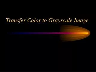
2. Related Work • Color transfer between images (Reinhard et al.) • Transfer in lαβ color space • Transferring Color to Grayscale Images (Welsh et al.) Transfer color from (b) to (a) Result (c)
2. Related Work • Local Color Transfer via Probabilistic Segmentation by Expectation-Maximization. (Yu-Wing Tai et al.) • proposes to solve this issue by presenting a probabilistic approach to conduct local color transfer. user still does not have enough direct control to specify the regions that should be modified and the colors to be transferred. • Colorization using Optimization. (Anat Levin et al.) scribbles by the user (left) colorized image (middle) groundtruth (right)
2. Related Work • Interactive Local Adjustment of Tonal Values (Lischinski et al.) (siggraph 2006) • They proposed a scribble-based local parameter editing tool. By using some strokes, the user can divide the image into several regions and locally adjust parameters such as brightness.
2. Related Work • Two-scale tone management for photographic look (Bae et al.) • They proposed a system that enables the user to transfer the "feeling" from one example to a target image, but it lacks of the ability of local control which our system provides.(histogram matching & textureness transfer)
2. Related Work • Bayesian Correction of Image Intensity with Spatial Consideration (Jia et al.) • They proposed a method that uses a pair of photos taken with different exposure conditions and combine two defective images to construct a high quality image of the scene, which may contain moving objects.
3. Stroke-based User Interface • An interactive and intuitive stroke-based user interface is provided for specifying corresponding regions on both the source and target photos. The color of the strokes indicates correspondence between the source and target photos. • the user can draw a stroke only on the source photo to preserve a region(background).
3. Stroke-based User Interface Terminology: • 、 : the pixels under the strokes that specify the regions to be preserved (background) and to be edited(foreground) on the sourcerespectively. • B 、F : the labels used to denote the background and foreground regions, respectively. • p: a pixelin an image. • cp : color of pixel p. • Ip : label of pixel p. • Is、It :source and target photosrespectively.
4. Background Preservation • Before applying the color transfer, in order to avoid unexpected modification of the background regions, we conduct a background preservation process to segmentthe source image into foreground and background regions based on the strokes and .
4. Background Preservation • The background preservation process is performed by an improved version of the graph cuts algorithm [BVZ01]. It is used to minimize the following energy function: • Np : neighboring pixels of p. • Ec(p): is the color term which is used to measure the conformity of the color of pixel p. • Es(p,q):is the smoothness term which is intended to maintain the edge in the image. • Ep(p):is the position term which utilizes the spatial information specified by the strokes in order to avoid discontinuous segmentation due to similar colors in different regions. (1)
4. Background Preservation • Ec(p): color term • The foreground strokes and the background ones are used to build 3D GMMs (Gaussian Mixture Models) to describe their color distributions. These are used to estimate whether the color of a pixel p is closer to the foreground or the background region. • GMM: 如果我們的資料X={x1,…,Xn}在d維空間中的分佈不是橢球狀,那麼就不適合以一個單一的高斯密度函數來描述這些資料點的機率密度函數。此時的變通方案,就是採用數個高斯函數的加權平均(Weighted Average)來表示。若以三個高斯函數來表示,則可表示成: 且
4. Background Preservation • Ec(p): color term (Video Object Cut and Paste) • For a given color c, its distance to the foreground GMMs is defined as: E1 = Ec Xr =1 (if pixel in the foreground region) Xr =0 (if pixel in the background region)
4. Background Preservation • Es(p,q): smoothness term (Progressive Cut) • uses the L2−norm distance of the neighboring pixels p and q in L∗a∗b∗ color space to measure the smoothness of the two pixels. If the color distance of the two pixels is small, it aims for making the labels of two pixels as same as possible. Otherwise, two different labels can be assigned to the two pixels. Xi、Xj: the labeling of i and j, respectively. Ci、Cj: the color of i and j, respectively. |xi – xj | allows to capture the contrast information only along the segmentation border.
4. Background Preservation • Ep(p): position term • If a pixel is closer to the foreground/background strokes, it is more likely that it should belong to the foreground/background regions. (2) r : the normalized distance difference from pixel p to the foreground or background strokes used to decide on the importance of the spatial information.
4. Background Preservation • By adding position term in energy function, we achieve much cleaner segmentation results and the background regions can be preserved precisely according to the background strokes drawn by the user. Finally,after the graph cuts process, each p ∈ Is is labeled by one lp ∈ {F,B} Without position term With position term
5. Multiple Local Color Transfer • Our approach for multiple local color transfer is to set a suitable local (pixel-wise) color transfer function , the color transfer is operated in the lαβ color space it can be performed separately in the three channels. • we treat the pixel-wise local color transfer functions as three linear processes: shifting, scaling and then shifting again denoted by u(p), f (p) and v(p) for updating the pixel p ∈ Is, respectively. Then, the gradient of the original source image Is is used to improve the pixelwise local color transfer functions and obtain the functions , and .
5. Multiple Local Color Transfer • Finally, the multiple local color transfer is defined as: (3)
5.1. Pixel-wise color transfer function • For the edit regions, since there are corresponding strokes and on both of the source and target images, we first build the Gaussian color model pairs and by using corresponding strokes with the same color (label) j ∈ F, respectively, so there are |F| local color transfer functions. we also build the background Gaussian color model for the preservation (background) regions on the source image based on the preservation (background) strokes . |F|=4 Background strokes(lightblue)
5.1. Pixel-wise color transfer function • C(cp, j) indicates by which ratio the color cp should be influenced from the j-th local color transfer function and is defined as: • is a Gaussian probability distribution function which is used to estimate the probability that the pixel’s color cp belongs to the Gaussian color model of the j-th stroke on the source image Is.
5.2. Gradient-guided color transfer function • we need to use the gradient of the original source image Is to improve the pixel-wise local color transfer functions u(p), f (p) and v(p) and obtain the gradient-guided color transfer functions, , and based on the following quadratic energy function proposed by Lischinski et al. (7) e=0.0001
6. Results Processing time:
7. Conclusion • In this paper, we have proposed an example-based photo enhancement system with an interactive and intuitive stroke-based user interface. Furthermore, a multiple local color transfer method is presented and applied to transfer color from the target examples to the source defect photo through gradient-guided local (pixel-wise) color transfer functions.