Download
1 / 15
150 likes | 320 Views
Switchgears Control Using SCADA System Based on PLC. Ch 5: Project Design. Ch 4: Switchgear Construction. Ch 1: Introduction to Programmable Logic Controllers. Contents. Ch 3: Main Components to Design SCADA System Based on PLC. Ch 2: Introduction to SCADA System.

E N D
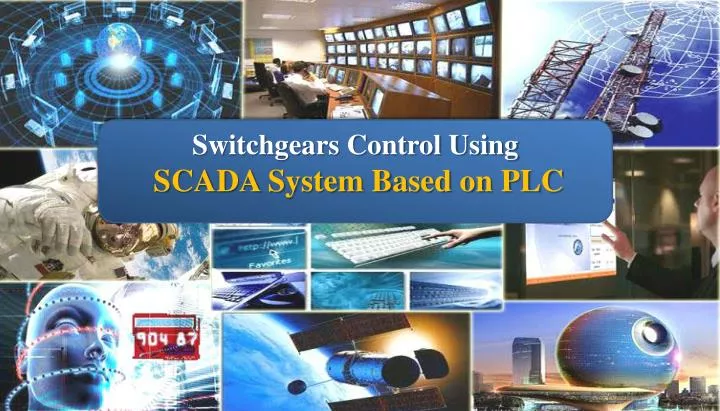
Switchgears Control Using • SCADA System Based on PLC
Ch 5: • Project Design • Ch 4: • Switchgear Construction • Ch 1: • Introduction to Programmable Logic Controllers Contents • Ch3: Main Components to Design SCADA System Based on PLC • Ch 2: • Introduction to SCADA System
CHAPTER ONE Introduction to Programmable Logic Controllers
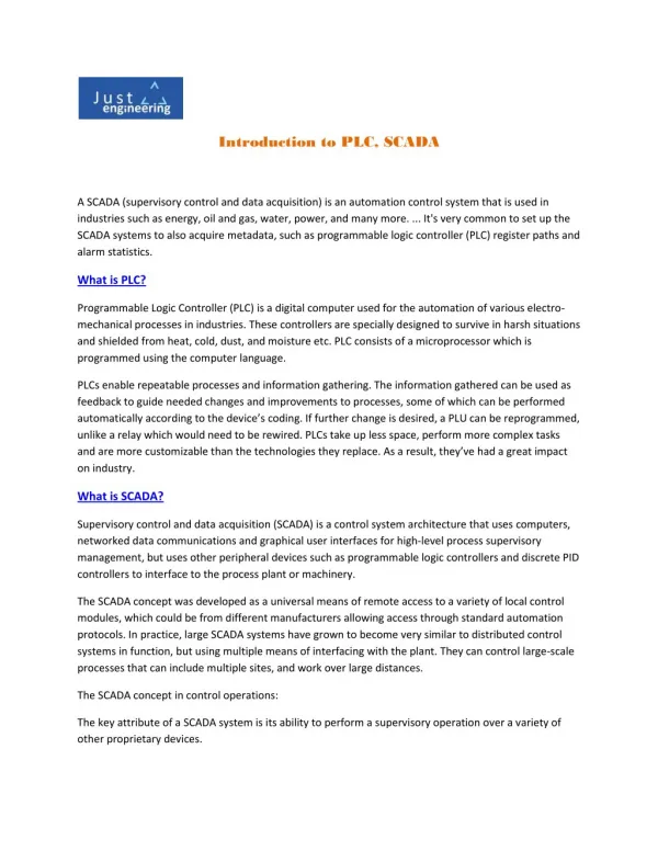
A-The Structure and Features of Programmable Logic Controllers: Programmable Logic Controllers (PLCs) have been used in industry, in one form or another, for the past twenty over years. The PLC is designed as a replacement for the hardwired relay and timer logic to be found in traditional control panels, where PLC provides ease and flexibility of control based on programming and executing logic instructions. The internal functions such as math instructions (Add, subtract, multiply and divide), timers and counters. The structure of a PLC can be divided into five parts: central processing unit (CPU), memory, input/output modules, power supply and programming terminal. Figure (1) - Programmable Logic Controller (PLC) Structure
Programmable Logic Controller (PLC) is an industrial computer control system that continuously monitors the state of input devices and makes decisions based upon a custom program to control the state of output devices. B- PLC Hardware Components 1- Central Processing Unit (CPU) 2-Memory 3- Input/output Module units 4- Power Supply 5- Programming Terminal C- How Does PLC Work? The CPU of the PLC executes the user program over and over again when it is in the RUN mode. The following figure shows the entire repetitive series of events: Figure (4) - PLC Scan Cycle
PLC Scan Cycle 1- Input scan 2- Program scan 3- Output scan D- Example Figure (5) shows the PLC program for AND operation between switch 1 and switch 2 and show the steps of scan cycle for execute this program. Figure (5) – Example for PLC Scan Cycle
E- Types of PLC programming languages • IEC 1131-3 is the international standard for programmable logic controller programming languages. • The following is a list of programming languages specified by this standard: • Ladder diagram (LD) • Sequential Function Charts (SFC) • Function Block Diagram (FBD) • Structured Text (ST) • Instruction List (IL) One of the primary benefits of the standard is that it allows multiple languages to be used within the same programmable logic controller. This allows the program developer to select the language best suited to each particular task. F- Introduction to Ladder Diagram Language Ladder Diagram is a type of graphic language for PLC, it has been used for a long period until today, and it is the oldest and most popular language for PLC. Each program statement is represented with a line called the rung that has all relevant inputs to the left and the output to the right. Figure (6) - Ladder Diagram The output device of a rung is energized if electric power can conceptually flow from the left side of the rung to the right. Input devices are assumed to block the flow of power if they are not activated
2- I/O Addressing • PLC manufactures use a variety of approaches in addressing the inputs, outputs, and other resources. • I/O addressing for AB PLC (Micrologix 1200 and Micrologix 1500) Figure (7) - I/O Addressing for AB PLC (Micrologix 1200 and Micrologix 1500)
3- Data Files for Micrologix 1200 Data files store numeric information, including I/O, status, and other data associated with the instructions used in ladder subroutines. The data file types are: Table (1) – Data File Types . Where:(1) File Number in BOLD (3, 4, 5, 6, 7, and 8) is the default. Additional data files of that type can be configured using the remaining numbers
. G- Introduction for Ladder Diagram Instructions 1- Input Instructions • Examine if Open (XIO) • Examine if Closed (XIC) . 2- Output Instruction • Output Energize (OTE) • Examples 1-Two Inputs OR Function The output is ON if any of the two inputs is ON. Ladder Diagram
2- Two Inputs AND Function The output is ON if both of the two inputs are ON. Ladder Diagram 3-Two Inputs NAND Function The output is ON if any of the two inputs is OFF. Ladder Diagram 4 -Two Inputs NOR Function The output is ON if both of the two inputs are OFF. Ladder Diagram
3-Timer Instructions • Timer Off-Delay (TOF) • Timer ON-Delay (TON) Use the TOF instruction to delay turning off an output. Use the TON instruction to delay turning on an output. 4- Math Instructions Most math instructions use three parameters; Source A, Source B, and Destination. The mathematical operation is performed using both Source values. The result is stored in the Destination. • ADD (Add) and Subtract (SUB) • Multiply (MUL) and Divide (DIV) 5- Program End (END) The END instruction must appear at the end of every ladder program.
6- Communication Instruction • Message (MSG) MSG is used to transfer data from one device to another. Any preceding logic on the message rung must be solved true before the message instruction can be processed. The example below shows a message instruction. If B3:0 is on (1), the MSG rung is true, and MG11:0 is not already processing a message; then MG11:0 is processed. • The Enable Bit (EN) is set when rung conditions go true and the MSG is enabled. • The Done Bit (DN) is set when the message is transmitted successfully. • The Error Bit (ER) is set when message transmission has failed. Access the message setup screen by double-clicking Setup Screen. This screen is used to setup “This PLC”, “Target PLC”, and “commands (Read and write)”.
Table (2) -Data Files of Reading and Writing for Micrologix 1200