Download
1 / 57
600 likes | 873 Views
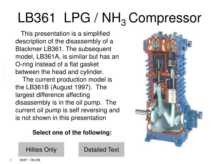
LB361 LPG / NH 3 Compressor. This presentation is a simplified description of the disassembly of a Blackmer LB361. The subsequent model, LB361A, is similar but has an O-ring instead of a flat gasket between the head and cylinder.

E N D
LB361 LPG / NH3 Compressor This presentation is a simplified description of the disassembly of a Blackmer LB361. The subsequent model, LB361A, is similar but has an O-ring instead of a flat gasket between the head and cylinder. The current production model is the LB361B (August 1997). The largest difference affecting disassembly is in the oil pump. The current oil pump is self reversing and is not shown in this presentation Select one of the following: Hilites Only Detailed Text
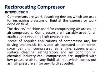
LB361 LPG / NH3 Compressor The LB361 compressor is suitable for many applications, but the most common is the transfer and vapor recovery of liquefied gases such as propane, butane, and anhydrous ammonia. The non-lubricated cylinder design of the LB361 allows the transfer of these products without contamination of the products and is capable of transferring up to 200 gallons per minute (760 lpm). Typically the LB361 is driven by a 10 or 15 HP driver in the 650 to 800 rpm range.
LITERATURE Be sure you have the proper literature before starting work on the compressor. Locate the parts list and Installation, Operation and Maintenance instructions. In addition, you may have received additional instruction sheets with your machine that further describe such items as valves and packing. Literature is available on the web at: blackmercompressor.com or from your Blackmer distributor.
Tools The tools normally required for small machine service will be adequate. A small strap wrench is useful as well as a good spanner. The Blackmer spanner p/n 790316 has 1/4” pins and is used for piston removal. A flat scraper and inside snap ring pliers are also needed. Blackmer offers a complete tool kit which has all of the hand tools necessary to dismantle the machine. On larger machines a small hoist might be needed for one man to do the job, depending on the environment. Generally, two men can handle the disassembly of any Blackmer machine.
Nameplate On the side of every Blackmer compressor is a nameplate which doubles as an access opening for inspecting the piston rod. The nameplate will show the compressor’s model number, serial number, ID number, and oil capacity. The compressor ID is a coded number that fully describes the compressor’s construction. Make certain that you have these identifying numbers when you call your Blackmer distributor for parts or service assistance.
LB361 Compressor Blackmer offers a variety of LPG transfer compressors. The LB362 is similar to the LB361 shown in this presentation but has two seals separated by a distance piece on each piston rod. Smaller models: LB161 / LB162 [7.5 bhp (5.5 kw)] Larger models: LB601 / LB602 [40 bhp (30 kw)] LB942 [50 bhp (37 kw)]
Pressure Gauges Blackmer compressors are typically fitted with a pressure gauge on both the suction and discharge. The gauges are fitted with a pulsation dampener to eliminate much of the vibration of the gauge needle making it easier to read and extending the life of the pressure gauge. Both suction and discharge pressure gauges should be installed on every compressor.
Valve Caps and Hold Down Screws Remove the valve caps to access the valves. Note the metal gasket under each cap; these should be replaced rather than reused. After the valve caps have been removed, the valve hold down screws can be removed with a 3/8” Allen wrench. To prevent possible damage to the valves during assembly, the hold down screws must be completely removed from the valve cover plates.
Valve Cover Plates . Once the valve caps and hold down screws have been removed, the cover plates can be removed. Note the the O–ring under the Cover Plate. These O-rings should be replaced, not reused any time the cover plates are removed. During assembly, the valve cover plates must be installed first, then the hold down screws installed.
Valves With the cover plates removed, the valve spacers, valves and gaskets may be taken out. A liquid relief device in the suction valve post helps protect the compressor in case liquid enters the cylinder area. It consists of a ball and spring relief valve which will allow liquid to be returned to the suction piping if necessary. The discharge valve is held in place by a solid post. Make certain the metal valve gaskets are removed with each valve as they may be difficult to see in the head. The valve gaskets are normally aluminum and must be replaced when the valves are removed.
Cylinder Head To remove the cylinder head, unbolt the two center head bolts from the top of the head and the six head bolts from the bottom of the head. The two center head bolts on models with flat head gaskets have metal gaskets which are normally not reusable. After the cylinder head bolts have been removed, the head may be lifted from the cylinder.
Head Gasket and Piston Nut The LB361 head is sealed to the cylinder with a flat head gasket. Carefully use a flat scraper or putty knife to remove the old gasket material before installing a new one. The LB361A and LB361B use O-rings to seal the cylinders. The piston nut is removed with an adjustable spanner. This spanner has two 1/4” pins which fit into holes in the top of the piston nut. Note the nylon locking device on the piston nut.
Piston Removal Once the piston nut has been removed, the spanner is used to unscrew the piston from the rod. Under each piston is a thick washer and one, or more, shims. These shims adjust the height of the piston in the cylinder. This is referred to as the “deck height”. Unless a major part has been changed, the deck height should not need adjustment. Changing the piston, crosshead assembly, cylinder body, main bearings or crankshaft may require adjustment of the deck height. Rotate the crankshaft to bring the other piston to top-dead-center for removal. Each piston is fitted with three piston rings. Each ring has a stainless steel expander between it and the piston. Install each piston ring with the bevel on the inside facing up. The ring and expander gaps should be staggered at 180° intervals during installation.
Cylinder With the pistons removed, the cylinder can be unbolted and removed to gain access to the packing boxes. Two O-rings seal the bottom of the cylinder. Notice the passage in the bottom of the cylinder between the bores. This allows gas to move from one cylinder to the other as the pistons move up and down.
Packing Box Removal The packing boxes are secured by a hold down screw which is removed with the same adjustable spanner that was used on the piston nut and piston. Note that the hold down screw also has a nylon insert that keeps it in place. The packing boxes may now be lifted off the rod. O-rings seal the bottom side of the packing boxes.
Packing Box disassembly To remove the seals (packing) from the box: Remove the top snap ring with a pair of inside snap ring pliers. Depress the spring with a screwdriver handle to make this operation easier.
Rod Seals With the snap ring removed, the top washer, spring, middle washer, seal rings, bottom washer and retainer ring can all be removed. The seal consists of three types of rings. One ring is a male ring, next a series of V-rings, then a female ring. On LB361 compressors, the spring and male ring will be at the top and the female ring will be at the bottom.
Piston Rod Inspection The piston rods and the top on the crossheads are visible through the opening when the nameplate is removed. The crosshead guide is secured to the crankcase by six bolts.
Crankcase and Crosshead With the crosshead guide removed, the crosshead / piston rods are visible. The flat gasket on top of the crankcase may require the use of a flat scraper to remove completely. The oil dipstick is located in the access cover. On current models, it is located adjacent to the access cover. The oil viscosity and capacity are found in the Instruction Manual.
Removal of the crankcase access cover and gasket permits access to the connecting rods. After the bottom cap of the connecting rod has been removed, the piston rod / crosshead and the top half of the connecting rod may be lifted off from above. Crosshead & Connecting Rod Removal
The connecting rod and crosshead assembly are separated by removing the wrist pin in a bench press. Note that the wrist pin has a plastic retainer plug on each end. The piston rod is permanently secured to the crosshead at the factory and no attempt should be made to separate them. Final machining is done to the assembled crosshead / rod which precludes their reassembly once separated. The grooves in the crosshead are lubrication channels. The small end of the connecting rod has a bronze bushing and is lubricated via and internal port running the length of the connecting rod. Crosshead and Connecting Rod
Crosshead and Connecting Rod (cont’d) A precision insert split shell bearing is located at the big [journal] end. Tabs on the bearing shells fit into slots in the rod and bearing cap. These retain the shells and align the oil feed holes. The LB361 uses a bronze bushing on a steel wrist pin at the small end of the conrod. The oil admission hole in the bearing or bushing must align with the oil supply hole in the connecting rod small end. When the bronze wrist pin bushing is replaced, it must be honed to final dimension after being pressed into the connecting rod The rod and cap are matched sets, do not mix. Match marks must align when assembling bearing cap to connecting rod.
The oil pressure adjustment screw includes an O-ring, lock nut, spring and ball. Turn the screw inward (clockwise) to increase the oil pressure setting. The oil pickup tube with washers, O-ring and strainer fits in the crankcase under the bearing carrier. If any foreign material is noticed in the strainer, its source should be quickly identified to prevent reoccurrence of the problem. The pipe plug next to the oil pickup tube opening is the crankcase oil drain. Some units will be fitted with an external oil filter (not shown). Oil Pressure adjustment, Strainer
Oil Pump This photo shows the oil pump used in the LB361 and LB361A. The LB361B uses a different pump. Remove the oil pump cover and O-ring to withdraw the oil pump. Notice the small O-ring on the pump shaft and the bronze bushing in the bearing carrier. The oil pump cover can be installed with either left or right rotation arrow visible. When installing the cover, make sure that the arrow at the TOP of the cover indicates the desired rotation direction.
The photo shows the bearing carrier / oil pump used in the LB361 and LB361A. The LB361B uses a different style. The entire bearing carrier / oil pump assembly, with gasket, can be removed intact. This allows the crankshaft to be removed. Note the slot in the end of the oil pump drive shaft. This slot must align with the drive tang in the end of the crankshaft during installation. Bearing Carrier
Remove the crosshead and connecting rod assemblies to proceed with the crankshaft removal. Notice the lubrication holes on the bearing journals. Also note the spray nozzles on the crankshaft. The spray nozzles lubricate the crosshead guide and the main [ roller ] bearings. The top of the crankcase is fitted with a breather which prevents entry of foreign material into the crankcase but allows the release of crankcase pressure. Crankshaft Removal
The bearing cover plate is on the flywheel side of the crankcase. Behind this plate are a series of shims which adjust the preload on the main bearings. These shims are normally reusable and the shim thickness will not have to be adjusted unless the crankshaft and / or main bearings are replaced. The bearing cover plate also contains a crankshaft oil seal. Bearing Cover Plate
End ofPresentation 1809 Century Avenue Grand Rapids, MI, USA 49503 Ph: 616-241-1611 Fax: 616-241-3752 www.blackmer.com
LB361 LPG / NH3 Compressor Liquid transfer / vapor recovery of: propane butane anhydrous ammonia Transfer without contamination Up to 200 GPM (760 lpm) Usually driven by 10 or 15 HP driver at 650 to 800 rpm
LITERATURE Have the proper literature at hand Parts lists Installation, Operation and Maintenance manual For literature: blackmercompressor.com Call your Blackmer distributor
Tools Use standard tools for small machines Blackmer adjustable spanner with 1/4” pins (p/n 790316) Inside snap ring pliers Blackmer tool kit available
Nameplate • Model number • Serial number • I.D. number • Defines construction • Oil capacity • Rod inspection access
LB361 Compressor Other Models Available: LB161/162 [7.5 bhp (5.5 kw)] LB362 double-seal LB601 / LB602[40 bhp (30 kw)] LB942 [50 bhp (37 kw)]
Pressure Gauges Always install! Suction & Discharge Pulsation dampener- extends gauge life & makes it easier to read.
Valve Caps and Hold Down Screws Cap gasket (metal) Remove screws with 3/8” Allen wrench Remove screw completely from cap!
Valve Cover Plates . • O-rings under cover plates are not normally reusable • Install the cover plates first, then the hold down screws
Valves Valve Spacers Liquid relief device - ball & spring Post Valves Valve gaskets - usually aluminum Always replace gaskets
Cylinder Head Two center head bolts have metal gaskets (LB361 only) Six bolts from the bottom
Head Gasket and Piston Nut Head Gasket (LB361) O-Ring (LB361A & LB361B) Remove old gasket material! Remove piston nut with 1/4” pin spanner Piston nut has nylon locking insert
Piston Removal Use spanner to unscrew piston Washer and shims adjust piston deck height Piston rings have expanders Bevel on inside of the ring faces up Install rings and expanders with staggered gaps
Cylinder Two O-rings seal the cylinder to the crankcase Under-piston channel between bores
Packing Box Removal Remove hold down screw with spanner Hold down screw has nylon locking insert O-rings seal bottom of packing box
Packing Box disassembly Depress spring with screwdriver Remove retainer ring with inside snap ring pliers
Rod Seals Female packing ring on bottom “V” - ring type Male packing ring on top Spring is on top of the packing
Piston Rod Inspection Piston rods and tops of the crossheads are visible through the nameplate opening
Crankcase and Crossheads Gasket between crankcase and guide Oil level dipstick
Access cover and gasket Remove lower bearing caps, lift crosshead and connecting rod assembly Crosshead & Connecting Rod Removal
Plastic retainer plugs Connecting rod has cast-in oil channel, big end to small end Connecting rod is Ductile Iron Cast iron crosshead Don’t remove piston rod from crosshead Crosshead and Connecting Rod