Download
1 / 15
160 likes | 353 Views
Review of waveguide components development for CLIC I. Syratchev, CERN.

E N D
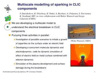
Review of waveguide components development for CLIC I. Syratchev, CERN
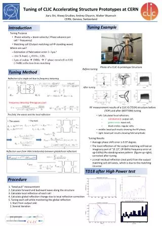
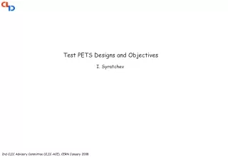
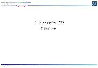
Many hundred thousands of waveguide components are needed for CLIC. The fabrication cost and waveguide network logistic are serious issues that are needed to be addressed to make an optimal RF waveguide distribution system. • The RF network in CLIC connects at a short distance (~ 0.5 m) broadband decelerating structure (PETS) and narrowband accelerating structure. Thus, all the waveguide components should be optimised to avoid parasitic circulation of the reflected signals in a system. • We have developed the special RF components to provide specific to CLIC operational properties. • In general, the particular choice of individual components could seriously affect the RF network layout and cost.
CLIC module RF network ON/OFF mechanism 3 dB splitter
Choke flange with circular groove To allow the independent transverse alignment of the two linacs in CLIC, the special, contact-free choke mode flanges are planned to be used. By specification, the 0.25 mm transverse misalignment should be tolerated. Throughout the design, reflection and matched radiation through the choke were minimized 11.424 GHz choke mode flange prototype has been tested at SLAC up to 90 MW 200 ns. Reflection S-parameters, dB choke Matched radiation In this geometry shift along narrow wall of the waveguide causes severe coupling to the trapped TM02 mode, which is close to the operating frequency. y ±0.5mm y ±0.25mm y x
Modified, double-sector choke flange y ±0.5mm S11, dB y x ±0.5mm x Frequency, GHz The new geometry allows for ±0.5mm sheer shift in both directions. It also can tolerate twist <10 and kink < 30. Matched radiation through the choke is below -40 dB. The slot is 2.5 mm wide.
Choke flange. Other applications Mini UHV gate valve • Ready to be used as a part of the compact RF/vacuum valve. • Building block of the RF phase stable long waveguide line. It will naturally compensate the thermal expansion without introducing extra RF phase advance. - Rotatable (3600) high RF power waveguide contact free joint (with circular grove). Designed for C-band medical accelerator. Polarizer converts H10 in rectangular WG into rotating H11 in a circular WG Choke flange
3dB H-plane splitter The 11.424 GHz version of the splitter was tested at SLAC up to 150 MW x 260 ns. Compact vacuum pumping port (design) S11, dB S-parameters, dB Radiation into the vacuum port
H-plane#1 3 dB hybrids (WR90) S13,S14 SLAC-type S11,S12 H-plane#2 KEK-type E-plane CLIC choice. 32 MV/m surface E-field at 100 MW.
Cross Potent family H-plane Hybrid solution E-plane
Compact design of the high RF power variable (mechanically) reflector ON OFF Transmitted RF power, dB Reflected Stroke 7.7 mm Piston position (gap width), mm The variable reflector is a core element of the PETS ON/OFF mechanism. It is activated when the local termination of the RF power production in PETS is required. Radiation through the chokes S-parameters, dB ON S-parameters, dB OFF
Influence of the external waveguide circuit bandwidth on the PETS RF power production Variable reflector with compact H20 -> H01 mode convertor PETS output signal Amplitude Amplitude Time, ns Time, ns Phase, deg. Phase, deg. Time, ns Time, ns
PETS ON/OFF operation ON OFF Power extracted from the drive beam The simulations have been done with HFSS, when the discrete current elements were representing the steady state current at a fixed frequency. Power to the structure
High RF power variable reflector. Other applications Variable splitter Variable attenuator (phase shifter) Load (short circuit)
SiC X-band moderate peak power ‘dry’ RF load with SiC absorber (design). The 15 MW peak RF power loads are the most common components in CLIC module. ~ 350 000 loads will be needed for 3 TeV CLIC option. 100 mm Max. E-fields on the ceramic surface 15 MW normal tangential
X-band high peak power (>50 MW) broadband ‘dry’ stainless steel load. We have received about 50 loads. The companies provide very reproducible results with reflection <-30dB at frequencies above 11.35 GHz. The loads have been tested up to 60MWx400ns (KEK) and 25MWx1600ns (SLAC). Design specifics Pulsed heating distributions along the load: H-field plot (quarter of the period) Green – design Red - measured Loads #36-39 The load half Load regular part cross section WR90 Matching taper E