Download
1 / 20
220 likes | 298 Views
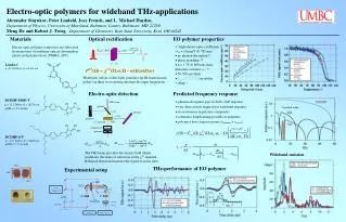
Chapter 7 Electro-optics Lecture 1 Linear electro-optic effect. 7.1 The electro-optic effect We have seen that light propagating in an anisotropic medium can be decomposed into its normal modes, or eigenwaves, which can be determined by the index ellipsoid:.

E N D
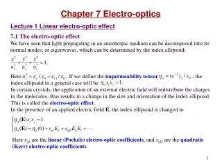
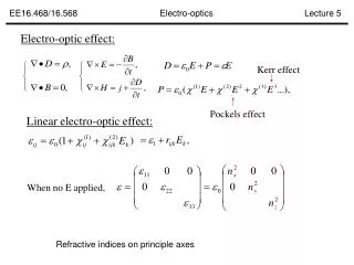
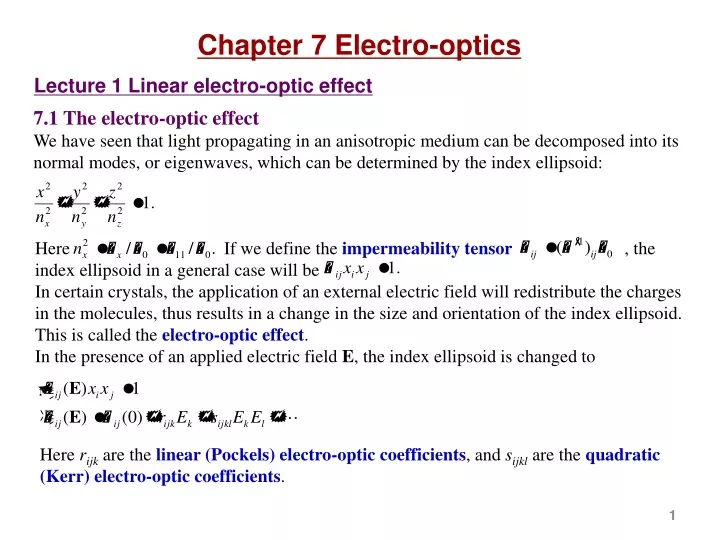
Chapter 7 Electro-optics Lecture 1 Linear electro-optic effect 7.1 The electro-optic effect We have seen that light propagating in an anisotropic medium can be decomposed into its normal modes, or eigenwaves, which can be determined by the index ellipsoid: Here If we define the impermeability tensor , the index ellipsoid in a general case will be In certain crystals, the application of an external electric field will redistribute the charges in the molecules, thus results in a change in the size and orientation of the index ellipsoid. This is called the electro-optic effect.In the presence of an applied electric field E, the index ellipsoid is changed to Here rijk are the linear (Pockels) electro-optic coefficients,andsijkl are thequadratic (Kerr) electro-optic coefficients.
From thermodynamic considerations the linear electro-optic coefficients rijk and the quadratic electro-optic coefficients sijkl have the following permutation symmetries: We therefore introduce the contracted indices to replace the paired interchangeable indices: The permutation symmetry reduces the number of the independent elements of rijk from 27 to 18, and that of sijkl from 81 to 36. A linear electro-optic effect is also called the Pockels effect,in which the change in the refractive index . Pockels effect is a second order nonlinear optical phenomenon. It only occurs in crystals that do not possess the inversion symmetry.For a crystal with the inversion symmetry, we can equivalently inverse the coordinates.
7.2 The linear electro-optic effect In an external electric field E the index ellipsoid is deformed into For the linear electro-optic effect, the change in the coefficients is given by Here rij is the linear electro-optic (or Pockels) coefficient, and r is called the electro-optic tensor. Depending on the symmetry of the crystal, many of the elements of the electro-optic tensor are 0, and some of them have the same or opposite values.Table 7.1 in the textbook lists the point groups of crystals. We have 7 crystal systems, which lead to 32 point groups. Table 7.2 lists the non-vanishing linear electro-optic coefficients of all the point groups. Table 7.3 gives the value of the linear optic-optic coefficients of some crystals.
Example 1: KDP (KH2PO4) crystal (negative uniaxial, point group). The E-field is in an arbitrary direction. The index ellipsoid is deformed and the xyz axes are no longer the principle axes. i) For the KDP crystal, if the E field is in the z direction, we have The index ellipsoid is tilted in the x-y plane.
It seems that we can simplify the problem by choosing a new principle axis system. We rotate the old coordinate system in the x-y plane counterclockwise by 45° and construct the new x′,y′,z′ system, that is The index ellipsoid in the new coordinate system is y y' x' x
ii) For the KDP crystal, if the applied field is in the x direction, then z z' The index ellipsoid is tilted in the y-z plane. We rotate the old coordinate system in the y-z plane counterclockwise by angle q, and construct the new x′,y′,z′ system. Suppose the index ellipsoid in the new coordinate system is nz' y q ny' y'
Example 2: LiNbO3 crystal (negative uniaxial, 3m point group).Suppose the E-field is in the z direction.
Lecture 2 Electro-optic modulation 7. 3 Electro-optic modulation In the example of the KDP crystal, if the external E-field is in the z direction, and the light is propagating in the z direction, the birefringence is Suppose the thickness of the plate is d, and the voltage applied is V=Ezd. The phase retardation is Since the retardation is proportional to the applied voltage, we can consequently convert the polarization state of the incident light into a desired polarization by choosing the appropriate voltage. This is called electro-optic retardation. For practical use, we write the retardation as is called the half-wave voltage, that is the voltage for obtaining a phase retardation of p. Example: For KDP at l=0.55 mm, no=1.50737, r63=10.6×10⁻¹² m/V, we have Vp=7.5 kV.
Electro-optic amplitude modulation A typical arrangement of an electro-optic amplitude modulator is shown in the figure. A KDP crystal is placed between two crossed polarizers. Also in the light path there is a quarter wave plate that introduces a fixed retardation of p/2. The input light is polarized in the x-direction. A voltage of is applied in the z direction of the crystal. This is called longitudinal electro-optic modulation since the applied electric field is parallel to the direction of light propagation. The total phase retardation is The transmission of the modulator is Therefore a small sinusoidal voltage will cause a sinusoidal modulation of the transmitted light intensity.
Transverse electro-optic modulation: We now consider the case where the applied electric field is perpendicular to the direction of light propagation, which is called the transverse electro-optic modulation. As shown in the figure, in a KDP crystal, the input light is polarized in the x′-z plane at 45° to each of the axes. The retardation at the output plane is then Compare to longitudinal electro-optic modulation, the advantages of transverse electro-optic modulation are 1) The retardation can be increased by using a longer crystal, or multiple crystals. 2) The filed electrodes do not interfere with the incident light beam.
Phase modulation of light In the case of KDP, if the external field is in the z direction, and the polarization of the input light is only in the x' direction, then the applied electric field will change the phase of the light, instead of its polarization. Suppose the field of the input light is , the applied electric field is , then the field of the output light is We see that lights at side bands are generated
Reading: Lecture 3 Quadratic electro-optic effect 7. 5 Quadratic electro-optic effect The quadratic electro-optic effect is a third order nonlinear effect, where the change in the refractive index is proportional to the square of the applied fields. Unlike the linear electro-optic effect, quadratic electro-optic effect occurs in crystals with any symmetry. Using contracted indices, the index ellipsoid in the presence of quadratic electro-optic effect is Table 7.4 lists the non-vanishing quadratic electro-optic coefficients of all the point groups. Table 7.5 gives the values of the quadratic optic-optic coefficients of some crystals.
Example 1: Kerr effect in an isotropic medium. Let the z axis be along the applied electric field. Here K is called the Kerr constant of the substance.
Example 2: Kerr effect in BaTiO3 (m3m). The applied electric field is