Download
1 / 50
500 likes | 508 Views
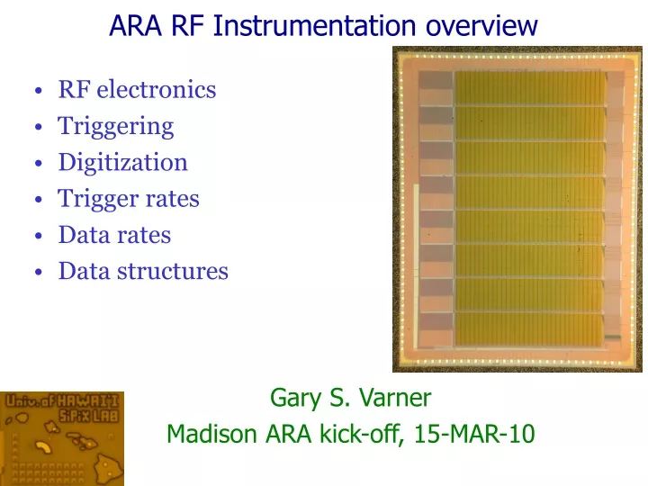
RF electronics Triggering Digitization Trigger rates Data rates Data structures. ARA RF Instrumentation overview. Gary S. Varner Madison ARA kick-off, 15-MAR-10. Cluster Station. ARA Readout Electronics. Uplink bandwidth (~1Mbit/s [wireless]) Multi-tier trigger

E N D
RF electronics • Triggering • Digitization • Trigger rates • Data rates • Data structures ARA RF Instrumentation overview Gary S. Varner Madison ARA kick-off, 15-MAR-10
ARA Readout Electronics • Uplink bandwidth (~1Mbit/s [wireless]) • Multi-tier trigger • Deeper sampling allows for “array” trigger (subthreshold)
ARA Readout Electronics: ASIC • Build on experience with “next generation” ASICs • Deeper storage depth, higher bandwidth? • Fewer timing alignment constants
Ice Radio Sampler (IRS) • Actually a fairly generic part • Follow-on evaluation of deeper storage [TARGET, others] (LABRADOR technology now >half decade old) • “2 stage” transfer mechanism (reduced calibration) • No amplifier on the input • Self-trigger capability (if useful) Collaborative effort with NTU
9 x 260 samples = 2340 storage cells ARA Trig/Dig Electronics - 15-MAR-2010 Convert all 2340 samples in parallel, transfer out on common 12-bit data bus 256 + 4 “tail” samples
Wilkinson ADC LAB3/IRS Digitization • No missing codes • Linearity as good as can make ramp • Can bracket range of interest 12-bit ADC • Excellent linearity • Basically as good as can make current source/comparator • Comparator ~0.4 – 2.1V; faster clock Run count during ramp ARA Trig/Dig Electronics - 15-MAR-2010 Modified! (self-counter) [0.7 GHz]
Ice Radio Sampler (IRS) Specifications • Strictly only 5 channels necessary • 4x antenna, 1x reference channels • Could interleave for twice depth, or multiple reference channels
5.82mm IRS Floorplan 7.62mm 8x RF inputs (die upside down) 32k storage cells per channel (512 groups of 64)
Sampling: 128 (2x 64 separate transfer lanes IRS Single Channel Recording in one set 64, transferring other (“ping-pong”) • Storage: 64 x 512 (512 = 8 * 64) • Wilkinson (32x2): 64 conv/channel
IRS Input Coupling • Input bandwidth depends on 2x terms • f3dB[input] = [2*p*Z*Ctot]-1 • f3dB[storage] = [2*p*Ron*Cstore]-1
IRS Input Coupling • Role of inductance
Sample Cell • Main element is buffer amp (OTA) • Relatively low current (10’s uA) operation possible
Constraint: kTC Noise Desire small C for better Input Coupling ARA Trig/Dig Electronics - 15-MAR-2010
Storage Cell • Diff. Pair as comparator • Only power on selected block
Another Constraint: Leakage Current Need small C for Input Coupling Can Improve? (readout faster) ARA Trig/Dig Electronics - 15-MAR-2010 Sample channel-channel variation ~ fA leakage typically
Input coupling sim (35fF sample) Onto chip (flip chip) ARA Trig/Dig Electronics - 15-MAR-2010 ~1 GHz input signal down -6dB voltage into storage cell
2 stage sampling speed sim ARA Trig/Dig Electronics - 15-MAR-2010 “RCObias” VadjP1,2 = RCObias; VadjN1,2 = VDD-RCObias
sampling speed measurement ARA Trig/Dig Electronics - 15-MAR-2010 Delta V RCObias Matches expectation
Temperature Dependence Reference for BLAB1 ASIC 6GSa/s 0.2%/degree C (servo-loop width) ARA Trig/Dig Electronics - 15-MAR-2010 Matches SPICE simulation
Wilkinson Clock Generation • Strictly only 5 channels necessary • 4x antenna, 1x reference channels • Could interleave for twice depth, or multiple reference channels
Wilkinson Recording Ripple counter (run as fast as can) Start = start 0.5-8GHz Clock
Wilkinson speed measurement ARA Trig/Dig Electronics - 15-MAR-2010 0.7 GHz 1.4us conversion to 10 bits
Output Bus Settling Time ARA Trig/Dig Electronics - 15-MAR-2010 ~8.5ns (10-90%) ~100MHz bus operation should be possible
Triggering • Need 9th channel for monitoring
Trigger output (LVTTL) Width measurement ARA Trig/Dig Electronics - 15-MAR-2010 For full (high) band, BW probably not good enough
Assume 8 channel (5 needed) • 5us/ADC cycle (8*64 samples/channel in parallel) • Transfer at 50MHz (20ns/sample) to FPGA • 1 conversion cycle ~ 5us (ADC) + 10us (transfer) • 256ns window (512 samples @ 2GSa/s) = 8 conv cycles • Total ~ 120us • Deadtimeless: 256ns (512 samples) of 16/32us (32k samples) held – sampling continues on others Conversion/readout speed
ARA Readout Electronics: Triggering • Maximize local and global sensitivity • Cluster (few 100ns window) [local] • Array prompt (10’s of us) [global, subthreshold] • Array rapid (10s of ms) [global, WF/TD low threshold] • High level (10’s of seconds) [global, WF/TD high threshold]
Diode detector Response ARA Trig/Dig Electronics - 15-MAR-2010 2.3s ~= 3.9 P/<P> Needs amplification!
Log-amp, tunnel diode test 100ps Pulse gen 0.2-1.2GHz receiver Hybrid splitter ARA Trig/Dig Electronics - 15-MAR-2010 trig AD8318 test board Tek TDS784C scope CH1 CH3 Coax tunnel diode detector 5ns rise time CH2 DC block • Can fast log-amps give same SNR as TD trigger? • Log-amp: V proportional to power • Uses multi-stage switching to get wide “linear” dynamic range, good stability • Tunnel-diode: square-law detector with long history in radio astronomomy & physics • But they are fussy to use!
Log-amp vs. tunnel diode SNR test ARA Trig/Dig Electronics - 15-MAR-2010 • Look at Vpeak to Vrms ratio for each device • Log-amp: • saturation evident • Loss of SNR fidelity below SNR~3 • TD: square-law behavior evident • Conclusions: log-amps may be problematic • We really need a true trigger efficiency test
Raw rates Singles rates
Raw rates Station coincidence
Additional constraint: causality Arriving radio front Use temporal/spatial constraints to reduce incoherent thermal accidentals and reject pathological directions (e.g. surface noise) Implemented as a 2D sliding window
ARA Readout Electronics: Triggering2 • Rates for each trigger type servo-looped • Cluster (few 100ns window) [local] • Array prompt (10’s of us) [global, subthreshold] • Array rapid (10s of ms) [global, WF/TD low threshold] • High level (10’s of seconds) [global, WF/TD high threshold]
Cluster Data Reduction (self-trigger) Raw Signals Level-2 Level-1 Level-3 Prioritizer? (+compress) Cluster Antenna Phi ARA Trig/Dig Electronics - 15-MAR-2010 Full band Pattern match 5-of-12 10Hz WF events/link 100’s kHz (L2L) 100’s Hz (L2H) 10-50Hz @ 6kBy/evt = 60-300kBy/s A few MHz (L1L) A few kHz (L1H) 12 RF channels @ 1.5By * 2.5GSa/s = 45 GBytes/s WF data = 50% HK/timestamp = 20% TD low-level = 10% High-level req = 20%
Readout rates • Constrained by actual link rate (assume 1Mb/s) • Shared bandwidth for Cluster self trigger and higher-level triggers • At 2GSa/s, 256ns window, pedestal subtracted: • Cluster event size ~ 12ch*512smp*1B ~ 6kB + overhead • 50% link BW dedicated to WF data • In addition to HK, forced and GPS-sync triggers
Readout concept has strong heritage • Build sample station for firmware/cal testbed development • Initially test with thermals (servo-loop software/firmware) • Key technology decisions • Tunnel diode versus RF power mon • IRS evaluation • Data and fast trigger links • Proposed architecture • Rather flexible • Optimize quickly -- timescale Summary
Back-up slides ARA Trig/Dig Electronics - 15-MAR-2010
Buffered LABRADOR (BLAB1) ASIC Measured Noise 1.6V dynamic range • 10 real bits of dynamic range, single-shot ARA Trig/Dig Electronics - 15-MAR-2010 1.45mV
Design Basis: Buffered LABRADOR (BLAB1) ASIC • Single channel • 64k samples deep, same SCA technique as LAB, no ripple pointer • Multi-MSa/s to Multi-GSa/s • 12-64us to form Global trigger ARA Trig/Dig Electronics - 15-MAR-2010 Arranged as 128 x 512 samples Simultaneous Write/Read 3mm x 2.8mm, TSMC 0.25um
BLAB1 Architecture 200ps/sample ARA Trig/Dig Electronics - 15-MAR-2010 FPGA-based TDC: 10-bits in 1us (300ps resolution)
BLAB1 Sampling Speed Can store 13us at 5GSa/s (before wrapping around) Single sample: 200/SQRT(12) ~ 58ps In practice, treat each row of 512 samples as independent 200ps/sample
BLAB1 Analog Bandwidth LAB3 ~ 900MHz -3dB ~300MHz • A few fixes (lower power, higher BW) • Multi-channel desired for BLAB2 Buffer amps