Download
1 / 35
350 likes | 371 Views
Particle Interactions with Matter. and. Detector Design Principles. Christoph Schäfer / CERN. Outline. Lecture 1 – Interaction of charged particles Lecture 2 – Momentum measurement, intro. to gaseous detectors Detector resolution Concept of p-measurement

E N D
Particle Interactions with Matter and Detector Design Principles Christoph Schäfer / CERN
Outline • Lecture 1 – Interaction of charged particles • Lecture 2 – Momentum measurement, intro. to gaseous detectors • Detector resolution • Concept of p-measurement • Ionization, drift, avalanche, choice of gas, operation modes • Detector types (MWPC, drift chambers, TPC, RPC, MPGD) • Lecture 3 – More interactions: electrons, photons, neutrons, neutrinos. Photon Detectors. • Lecture 4 – Organic Scintillators, detector testing, detector systems
Detector resolution – some general observations Energy deposition in detectors happens in small discrete and independent steps. Even in the case of a well defined and constant amount of energy deposited in a detector , the achievable resolution in terms of energy, spatial coordinates or time is constrained by the statistical fluctuations in the number of charge carriers (electron-hole pairs, electron-ion pairs, scintillation photons) produced in the detector. In most cases, the number of charge carriers nc is well described by a Poisson distribution with mean m = <nc> Example: average 1 earthquake in 100 years Probability to not have an earthquake in the next 100 years? m The variance of the Poisson distribution is equal to its mean value. Poisson distribution for m = 5.0 standard deviation nc
Detector resolution For large m values, (e.g. m > 10) the Poisson distribution becomes reasonably well approximated by the symmetric and continuous Gauss distribution. m s FWHM Often used to characterize detector resolution: FWHM nc The energy resolution of many detectors is found to scale like Often, also time and spatial resolution improve with increasing <nc>
Energy resolution – Fano factor Case 1: particle traversing the detector The measured energy deposition E is derived from the number of charge carriers (e.g. e-h or e-ion pairs) (Poisson limit) We ignore here many effects which, in a real detector, will degrade the resolution beyond the Poisson limit ! Dx In particular, depending on the thickness Dx and density, there may also be strong Landau tails.
Energy resolution – Fano factor Case 2: Particle stops in the detector, or (x-ray) photon is fully absorbed the energy deposition in the detector is fixed (but may vary from event to event). Eg F = Fano factor Ep Ugo Fano, Phys. Rev. 72 (1947), 26–29 For a formal derivation: See e.g. book by C. Grupen, pages 15-18. For a physics motivated derivation: See e.g. H. Spieler, Heidelberg Lecture notes, ch. II, p25… (1912 - 2001) The fluctuation in the number of produced charge carriers nc is constrained by energy conservation. But in a Silicon detector phonons can be created having a much less excitation energy and thus are produced massively resulting is a reduction of the variance. FSi = 0.12, Fdiamond = 0.08. The detector resolution is (can be?) improved by a factor
Detector spatial resolution Resolution of a discrete detector x 0 x wx Consider one strip only (for simplicity at x = xd = 0): For every recorded hit, we know that the strip at x =0 was hit, i.e. the particle was in the interval wx Assume a detector consisting of strips of width wx, exposed to a beam of particles. The detector produces a (binary) signal if one of the strips was hit. What is its resolution sx for the measurement of the x-coordinate?
Detector resolution Resolution of a discrete detector (cont.) We have tacitly assumed that the particles are uniformly distributed over the strip width. More generally, a distribution function needs to be taken into account D(x) D(x) 1 1 -wx/2 wx/2 x -wx/2 wx/2 x You will see such expressions many times
B B q B B B>0 B>0 Momentum measurement x z y pL x y B=0
Momentum measurement We measure only p-component transverse to B field ! a the sagitta s is determined by 3 measurements with error s(x): for N equidistant measurements, one obtains(R.L. Gluckstern, NIM 24 (1963) 381) (for N ≥ ~10)
s (p)/p meas. total error s (p)/p MS s (p)/p p Momentum measurement What is the contribution of multiple scattering to ? remember , i.e. independent of p ! Example: pt = 1 GeV/c, L = 1m, B = 1 T, N = 10 s(x) = 200mm: More precisely: Assume detector (L = 1m) to be filled with 1 atm. Argon gas (X0 = 110m), Optimistic, since a gas detector consists of more than just gas!
A more realistic example: CMS Silicon Tracker • B=3.8T, L=1.25m, average N ≈ 10 layers, • Average resolution per layer ≈ 25mm, • sp/p = 0.1 % momentum resolution (at 1 GeV) • sp/p = 10 % momentum resolution (at 1 TeV) r ≈ 1.25m Material budget (Si, cables, cooling pipes, support structure…) • B=3.8T, L=1.25m, t/X0 ≈ 0.4-0.5 @ h < 1 • sp/p = 0.7% from multiple scattering (h = pseudo rapidity: )
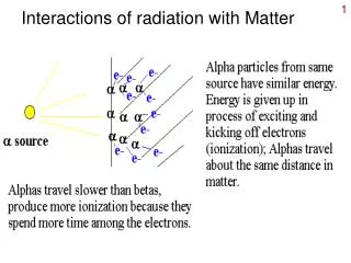
Ionization of Gases Primary ionization Total ionization Number of primary electron/ion pairs in frequently used gases. Fast charged particles ionize atoms of gas. Often, the resulting primary electrons will have enough kinetic energy to ionize other atoms. Lohse and Witzeling, Instrumentation In High Energy Physics, World Scientific,1992 ntotal -number of created electron-ion pairs DE= total energy loss Wi= effective <energy loss>/pair
Ionization of Gases • The actual numberof primary electron/ion pairs is Poisson distributed. Poisson distribution for m = 2.5 The detection efficiency is therefore limited to : For thin layers edet can be significantly lower than 1. For example for 1 mm layer of Ar nprimary= 2.5 → edet = 0.92 . • Consider a 10 mm thick Ar layer • nprimary= 25 → edet = 1 • ntotal= 80-100 • 100 electron/ion pairs created during ionization process are not easy to detect. • Typical noise of the amplifier ≈ 1000 e- • → we will increase the number of charge carriers by gas amplification .
Single Wire Proportional Chamber Electrons liberated by ionization drift towards the anode wire. Electrical field close to the wire (typical wire Ø ~few tens of mm) is sufficiently high for electrons (above 10 kV/cm) to gain enough energy to ionize further → avalanche – exponential increase of number of electron ion pairs. Attention: Wire is a line charge! anode e- primary electron C – capacitance/unit length Cylindrical geometry is not the only one able to generate strong electric field: parallel plate strip hole groove
Single Wire Proportional Chamber Multiplication of ionization is described by the first Townsend coefficient a(E) Ar-CH4 = number of e-ion pairs produced by an Electron along a path of 1 cm dn = n·a dx l – mean free path A. Sharma and F. Sauli, NIM A334(1993)420 (E/p = reduced electric field) a(E) is determined by the excitation and ionization cross sections of the electrons in the gas. It depends also on various and complex energy transfer mechanisms between gas molecules. There is no fundamental expression for a(E) → it has to be measured for every gas mixture. Amplification factor or Gain S.C. Brown, Basic data of plasma physics (MIT Press, 1959)
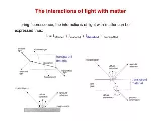
SWPC – Choice of Gas In noble gases, ionization is the dominant process, but there are also excited states. De-excitation of noble gases only via emission of photons; e.g. 11.6 eV for Ar. This is above ionization threshold of metals, e.g. Cu 7.7 eV. S. Biagi, NIM A421 (1999) 234 ELASTIC IONIZATION SUM OF EXCITATION new avalanches permanent discharges ! ELASTIC Solution: addition of polyatomic gas as a quencher Absorption of photons in a large energy range (many vibrational and rotational energy levels). IONIZATION Energy dissipation by collisions with gas molecules or dissociation into smaller molecules. Photon energy <1eV = infrared radiation CO2 has a high cross section for infrared = greenhouse effect! vibrational levels excitation levels
SWPC – Operation Modes • ionization mode – full charge collection, but no • charge multiplication; • gain ~ 1 • proportional mode – multiplication of ionization • starts; detected signal proportional to original • ionization → possible energy measurement (dE/dx); • secondary avalanches have to be quenched; • gain ~ 104 – 105 • limited proportional mode (saturated, streamer) – • strong photoemission; secondary avalanches • merging with original avalanche; requires strong • quenchers or pulsed HV; large signals → simple • electronics; • gain ~ 1010 • Geiger mode – massive photoemission; full length • of the anode wire affected; discharge stopped by • HV cut; strong quenchers needed as well
Multiwire Proportional Chamber Simple idea to multiply SWPC cell : Nobel Prize 1992 First electronic device allowing high statistics experiments !! Typical geometry 5mm, 1mm, 20 mm Normally digital readout : spatial resolution limited to for d = 1 mm sx = 300 mm G. Charpak, F. Sauli and J.C. Santiard
CSC – Cathode Strip Chamber Precise measurement of the second coordinate by interpolation of the signal induced on pads. Closely spaced wires makes CSC fast detector. s = 64 mm Center of gravity of induced signal method. CMS Space resolution
HV GND readout strips HV resistive electrode gas gap GND resistive electrode readout strips RPC – Resistive Plate Chamber useful gap Operation at high E-field streamer mode. Rate capability strong function of the resistivity of electrodes. 2 mm A. Akindinov et al., NIM A456(2000)16 s = 77 ps MRPC floating electrodes Multigap RPC - exceptional time resolution suited for TOF and trigger applications Time resolution
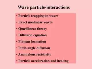
Ds, Dt s, t Drift and Diffusion in Presence of E field E=0 thermal diffusion A+ e- E>0 charge transport and diffusion Electric Field Electron swarm drift Drift velocity Diffusion
Drift and Diffusion of Electrons in Gases Large range of drift velocity and diffusion: F. Sauli, IEEE Short Course on Radiation Detection and Measurement, Norfolk (Virginia) November 10-11, 2002 Rule of thumb: vD (electrons) ~ 5 cm/ms = 50 mm / ns. Ions drift ~1000 times slower.
Drift Chambers Spatial information obtained by measuring time of drift of electrons Measure arrival time of electrons at sense wire relative to a time t0. Need a trigger (bunch crossing or scintillator). Drift velocity independent from E. F. Sauli, NIM 156(1978)147 Advantages: smaller number of wires less electronics channels. Resolution determined by diffusion, primary ionization statistics, path fluctuations and electronics.
Drift Chambers Planar drift chamber designs Essential: linear space-time relation; constant E-field; little dpendence of vDon E. U. Becker in Instrumentation in High Energy Physics, World Scientific
neg. high voltage plane particle track E liberated e- Z (e-drift time) gating plane cathode plane anode plane pads Y Induced charge on the plane X TPC – Time Projection Chamber • Time Projection Chamber • full 3D track reconstruction: • x-y from wires and segmented • cathode of MWPC (or GEM) • z from drift time • momentum resolution • space resolution + B field • (multiple scattering) • energy resolution • measure of primary ionization B
TPC – Time Projection Chamber Positive ion backflow modifies electric field resulting in track distortion. Solution : gating Prevents electrons to enter amplification region in case of uninteresting event; Prevents ions created in avalanches to flow back to drift region. gate open gate closed gating plane cathode plane anode wires readout pads ALEPH coll., NIM A294(1990)121
E E E E 88µs 560 cm 520 cm TPC – Time Projection Chamber Alice TPC HV central electrode at –100 kV Drift length 250 cm at E = 400 V/cm Gas Ne-CO2 90-10 Space point resolution ~500 mm dp/p = 2%@1GeV/c; 10%@10 GeV/c Events from STAR TPC at RHIC Au-Au collisions at CM energy of 130 GeV/n Typically ~2000 tracks/event
MSGC – Microstrip Gas Chamber Thin metal anodes and cathodes on insulating support (glass, flexible polyimide ..) 200 mm Problems: High discharge probability under exposure to highly ionizing particles caused by the regions of very high E field on the border between conductor and insulator. Charging up of the insulator and modification of the E field → time evolution of the gain. slightly conductive support insulating support R. Bellazzini et al. IN PRESENCE OF a PARTICLES • Solutions: • slightly conductive support • multistage amplification
Micropattern Gas Detectors (MPGD) • General advantages of gas detectors: • low mass (in terms of radiation length) • large areas at low price • flexible geometry • spatial, energy resolution … • Main limitation: • rate capability limited by space charge defined by • the time of evacuation of positive ions • Solution: • reduction of the size of the detecting cell (limitation • of the length of the ion path) using chemical • etching techniques developed for microelectronics • and keeping at same time similar field shape. MWPC scale factor 1 MSGC 5 MGC 10 R. Bellazzini et al.
Micromegas – Micromesh Gaseous Structure Metal micromesh mounted above readout structure (typically strips). E field similar to parallel plate detector. Ea/Ei ~ 50 to ensure electron transparency and positive ion flowback supression. 100 mm micromesh s = 70 mm Ei Ea Space resolution
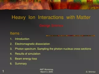
I+ 5 µm e- 50 µm Induction gap e- 55 µm 70 µm GEM – Gas Electron Multiplier Ions e- Thin, metal coated polyimide foil perforated with high density holes. Electrons are collected on patterned readout board. A fast signal can be detected on the lower GEM electrode for triggering or energy discrimination. All readout electrodes are at ground potential. Positive ions partially collected on the GEM electrodes.
GEM – Gas Electron Multiplier Full decupling of the charge ampification structure from the charge collection and readout structure. Both structures can be optimized independently ! Cartesian Compass, LHCb A. Bressan et al, Nucl. Instr. and Meth. A425(1999)254 Small angle 33 cm Hexaboard, pads MICE Totem Compass Both detectors use three GEM foils in cascade for amplification to reduce discharge probability by reducing field strenght. Mixed Totem
Limitations of Gas Detectors Classical ageing Avalanche region → plasma formation (complicated plasma chemistry) • Dissociation of detector gas and pollutants • Highly active radicals formation • Polymerization (organic quenchers) • Insulating deposits on anodes and cathodes Anode: increase of the wire diameter, reduced and variable field, variable gain and energy resolution. Cathode: formation of strong dipoles, field emmision and microdischarges (Malter effect).
Limitations of Gas Detectors Solutions: carefull material selection for the detector construction and gas system, detector type (GEM is resitant to classical ageing), working point, non-polymerizing gases, additives supressing polymerization (alkohols, methylal), additives increasing surface conductivity (H2O vapour), clening additives (CF4). Discharges Field and charge density dependent effect. Solution: multistep amplification Space charge limiting rate capability Solution: reduction of the lenght of the positive ion path Insulator charging up resulting in gain variable with time and rate Solution: slightly conductive materials