Download
1 / 43
430 likes | 526 Views
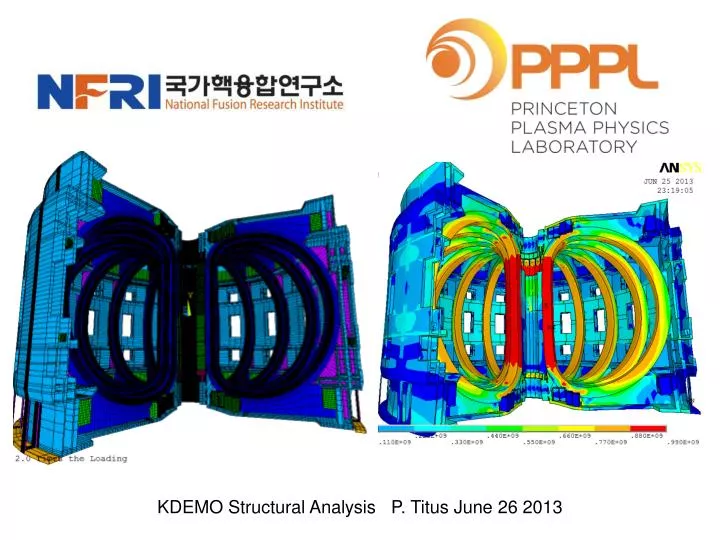
KDEMO Structural Analysis P. Titus June 26 2013. KDEMO Poloidal Coil Analysis. ! KDEMO coil axisymmetric analysis pfcb 21 1, 1.52,0.70,.9,1.3,8,10 !CS1 2, 1.52,2.10,.9,1.3,8,10 !CS2 3, 1.52,3.50,.9,1.3,8,10 !CS3 4, 1.52,4.90,.9,1.3,8,10 !CS4 5, 2.98,8.31,.60,1.25,8,10 !PF1

E N D
KDEMO Poloidal Coil Analysis ! KDEMO coil axisymmetric analysis pfcb 21 1, 1.52,0.70,.9,1.3,8,10 !CS1 2, 1.52,2.10,.9,1.3,8,10 !CS2 3, 1.52,3.50,.9,1.3,8,10 !CS3 4, 1.52,4.90,.9,1.3,8,10 !CS4 5, 2.98,8.31,.60,1.25,8,10 !PF1 6, 3.66,8.31,.60,1.25,8,10 !PF2 7, 4.34,8.59,.60,1.25,8,10 !PF3 8, 5.02,8.75,.60,1.25,8,10 !PF4 9, 12.96,7.50,.849,1.5 ,8,10 !PF5 10, 14.88,2.95,.4,.5 ,8,10 !PF6 11, 14.88,-2.95,.4,.5,8,10 !PF6 12, 12.96,-7.50,.849,1.5,8,10 !PF5 13, 5.02,-8.75,.60,1.25,8,10 !PF4 14, 4.34,-8.59,.60,1.25,8,10 !PF3 15, 3.66,-8.31,.60,1.25,8,10 !PF2 16, 2.98,-8.31,.60,1.25,8,10 !PF1 17, 1.52,-4.90,.9,1.3,8,10 !CS4 18, 1.52,-3.50,.9,1.3,8,10 !CS3 19, 1.52,-2.10,.9,1.3,8,10 !CS2L 20, 1.52,-0.70,.9,1.3,8,10 !CS1L 21, 6.1,0,2.1,4.2,8,10 !Plasma pfcu 21,3,1,1.0 1,7.68,3.11,-1.55 2,7.68,3.11,-1.55 3,9.65,3.25,-2.25 4,9.65,3.25,-2.25 5,2.323,4.506,5.715 6,3.171,6.235,7.909 7,3.475,6.169,7.897 8,3.663,5.286,6.914 9,0.021,-13.70,-15.95 10,0.184,0.135,-0.223 11,0.184,0.135,-0.223 12,0.021,-13.70,-15.95 13,3.663,5.286,6.914 14,3.475,6.169,7.897 15,3.171,6.235,7.909 16,2.323,4.506,5.715 17,9.65,3.25,-2.25 18,9.65,3.25,-2.25 19,7.68,3.11,-1.55 20,7.68,3.11,-1.55 21,0,13,13
Poloidal Field Vectors Kdm1.dat Not 11 Tesla Kdm3.dat Kdm2.dat
Nodal ForceVectors Kdm1.dat Kdm3.dat Kdm3.dat
DEMO CS CICC Parameter (Corner Channel) • Cable Pattern: (2SC+1Cu)x3x4x4x6 [576 SC Strand + 288 Cu Strand] • Void Fraction : 35.85% • Strand : • ITER Type (Jc ~ 1000A/mm2) Nb3Sn Strand • Cu/Non-Cu = 1.0 • NO COOLING SPIRAL Corner Channel • Jacket Thickness : 5 mm • Insulation : 2.0 mm (with Voltage Tap) • 0.1 mm Kapton 400% • 0.4 mm S-glass 400% • Twist Pitch • 1st Stage 20 ± 5 mm • 2ndStage 45 ± 10 mm • 3rdStage 85 ± 10 mm • 4thStage 150 ± 15 mm • 5thStage 355± 20 mm • Wrapping Tape Thickness • Sub-cable : 0.08 mm 40% • Sub-cable wrap width : 15 mm • Cable : 0.5 mm 60% • Final wrap width : 7 mm R 3 2 5 Insulation 54 50 40 Jacket 34 30 20 DEMO CS CICC Cross-section
Initial Magnetization Kdm1.txt, kdem1.dat Based on the hoop multiplier 76.1*2.64 = 200 MPa
ITER CS Conductor near Butt Weld ITER CS He Penetration Starts at 662 then propagates into region that is about 200 MPa Starts at 356 then propagates into region that is about 325 MPa
Initial Magnetization Check of Average Hoop Stress Average Hoop Stress = 5.327e7/1.17/1e6=45.5MPa
Based on the CS hoop multiplier Applied to PF5 90.6*2.64 = 240 MPa
Based on the CS hoop multiplier Applied to PF5 126*2.64 = 332 MPa
TF Case and Winding Pack Analysis TF Case 2/3* yield = 666 MPa ½ Ultimate = 750 Mpa 1/3 Ultimate = 500 MPa Sm, Primary Membrane Allowable = 666 Mpa According to ITER MSDC The average stress in the inner leg case should satisfy this Allowable
Meshed areas from Tom’s Parasolids Initial Geometry Without Added Outer Structures
kdm1 Field Vectors
Nodal Force Vectors Field Vectors
Kdm1 Tresca Stress TF Case 2/3* yield = 666 MPa ½ Ultimate = 750 Mpa 1/3 Ultimate = 500 MPa Allowable = 666 Mpa According to ITER MSDC
TF Case 2/3* yield = 666 MPa ½ Ultimate = 750 Mpa 1/3 Ultimate = 500 MPa Allowable = 666 Mpa According to ITER MSDC
Added Upper Structure Added Outer Structure Added Lower Structure
Model with Added Structure Model with 16 fold Symmetry, 12 fold symmetry Expansion
TF Case 2/3* yield = 666 MPa ½ Ultimate = 750 Mpa 1/3 Ultimate = 500 MPa Allowable = 666 Mpa According to ITER MSDC Results with Added Structure Still Doesn’t Pass
From the NSTX structural criteria. "An exception to this elastic analysis approach can be when the nature of the structure and its loading make it difficult to decompose the stresses into the above mentioned categories. In such an instance, a detailed, non-linear analysis that accounts for elastic-plastic behavior, frictional sliding and large displacement shall be used to determine the limit load on the structure. The limit load is that load which represents the onset of a failure to satisfy the Normal operating condition as described in Section I-2.6. The safety factor of limit load divided by the normal load shall be greater than 2.0.“ Similar wording is in the ITER Magnet Structural Design Criteria (MSDC)
Try Elastic-Plastic Limit Analysis. Must Show a factor of 2 on failure (Non-Convergence in ANSYS Model)
An approximation of the options suggested by Keeman Kim is analyzed. The model Inner leg has an inner radius of 2.0m and OR = 3.14m. The inner wedged section is .286 m thick. This section can support the centering load but depending on the position of the outer leg and the stiffness/strength of the outer structures, the inner leg cross section could be acceptable. However with only 27% of the vertical separating force on the inner leg, the cross section is inadequate. Limit analysis is used to evaluate the section. With only the centering load, the load factor is above 3. With 27% of the bursting force applied to the inner leg, the load factor goes to only 1.5. It should be at least 2.0. Heavy/stronger, and stiffer outer structures are needed to support ,most of the vertical bursting load.
The Bursting Force – is Applied on the Inner Leg Cross Section at a Coupled Node Set. In the runs with the bursting load, 200MN is applied of the 11946/16 = 750 MN per coil, or 27% – The remainder is assumed taken by the outer structures
316 SST Stress Strain Conductor Stress Strain Model Materials 16 Fold Symmetry Expansion
Bmax=13.13 ANSYS Nodal Forces
ANSYS CP’s on Top Face ANSYS Displacement Constraints
Vertical Separating Force is Applied on One of the Coupled Nodes on the Top Face
Von Mises Stress 2.5*Load Von Mises Plastic Strain 2.5*Load
Excluding Vertical Separating Force /DSCALE,1,20 (20 times actual)
Including Scaled 200MN Vertical Separating Force /DSCALE,1,20 (20 times actual)
Including Scaled Vertical Separating Force Radial Displacement Under Increasing Load Collapses at Step 3 or 1.5 times the Nominal Load Excluding Scaled Vertical Separating Force Radial Displacement Under Increasing Load Collapses at Step 7 > 3 times the Nominal Load
Excluding Scaled Vertical Separating Force Radial Displacement Under Increasing Load Collapses at Step 7 > 3 times the Nominal Load Excluding Scaled Vertical Separating Force Plastic Strain in the Nose Remains Elastic up to Load Step 4, 2.0Times the Nominal Load
Conductor Total Strain Normal Loading Including 200MN Vertical Separating Force
Normal Loading Including 200MN Vertical Separating Force Radial Total Strain Axial Total Strain Theta Total Strain Von Mises Total Strain
Normal Loading Including 200MN Vertical Separating Force Insulation Von Mises Stress