Download

1 / 51
560 likes | 640 Views
DIE DESIGN. Cross 11, Tapovan Enclave Nala pani Road, Dehradun 248001 Email: info@iskd.in Contact : +918979066357, +919027669947. Die Design.

E N D
DIE DESIGN Cross 11, Tapovan Enclave Nalapani Road, Dehradun 248001 Email: info@iskd.inContact : +918979066357, +919027669947
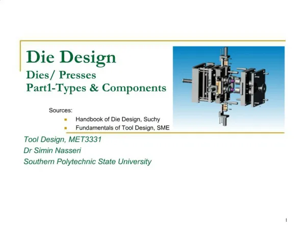
Die Design Die design is an emerging field in which cost-effective methods are employed for the production of a diverse range of things. CONSTRUCTION A die is basically made in two sections the fixed die half and the ejector dies half. Tool and die makers are a class of machinists in the manufacturing industries. They make jigs, fixtures, dies, molds, machine tools, cutting tools, gauges, and other tools used in manufacturing processes Different type of dies • Bending. Bending is the process of deforming a base material through pressure from a die. • Blanking. Blanking is a way of cutting flat material by trimming it from its exterior edge. • Broaching. A broaching die can be a useful option for shaping material that is too thick or hard to be cut by other means. ... • Bulging.
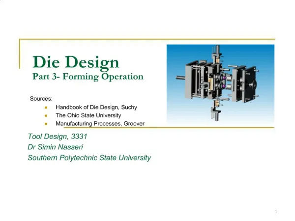
The die's cutting and forming sections typically are made from special types of hardenable steel called tool steel. Dies also can contain cutting and forming sections made from carbide or various other hard, wear-resistant materials.Different materials are used to make die in die and punches. The material used in configuration of a die and punch machine varies from aluminum alloy to pre-hardened steel. The HOLDER is preferably made of S400, S50C (S55C), FC250, A7075. While the backing plate is made of SK3, SK5, SKS3, AND S50C.Forming dies are typically made by tool and die makers and put into production after mounting into a press. The die is a metal block that is used for forming materials like sheet metal and plastic3 Different Methods for Forgings. Rolled Ring Forging. ...Rolled Ring Forging. Rolled ring forging is a process that uses two curved dies to deform the metal. ...Closed Die Forging. Closed die forging is a process that shapes a metal part by forcing it into the contours of a die. ...Open Die Forging.
What is CFD?Prediction fluid flow with the complications of simultaneous flow of heat, mass transfer, phase change, chemical reaction, etc using computers History • Since 1940s analytical solution to most fluid dynamics problems was available for idealized solutions. Methods for solution of ODEs or PDEs were conceived only on paper due to absence of personal computer. • Daimler Chrysler was the first company to use CFD in Automotive sector. • Speedo was the first swimwear company to use CFD. • There are number of companies and software's in CFD field in the world. Some software's by American companies are FLUENT, TIDAL, C-MOLD, GASP, FLOTRAN, SPLASH, Tetrex, ViGPLOT, VGRID, etc.
Machine die A die cutting machine is a machine designed to cut materials, such as paper, fabric, or metal, to a specific shape. ... Cutting dies are purchased separately to be used in the machine, which cut the desired material. Cutting dies come in all shapes, sizes, and designs. Progressive Die Progressive die stamping is a metal forming process widely used to produce parts for various industries, such as automotive, electronics and appliances. Progressive die stamping consists of several individual work stations, each of which performs one or more different operations on the part.
Difference Between Mold & Dye Moulds tend to be used to produce products that need to be hollow in the middle, whereas dies are used to stamp solid products out of media such as steel. DIE IS a block of metal with a special shape or with a pattern cut into it that is used for shaping other pieces of metal such as coins or for making patterns. Die Casting The mold cavity is created using two hardened tool steel dies which have been machined into shape and work similarly to an injection mold during the process. Most die castings are made from non-ferrous metals, specifically zinc, copper, aluminium , magnesium, lead, pewter, and tin-based alloys.
Difference between Casting and Molding Molding is the process of manufacturing by shaping liquid or pliable raw material using a rigid frame called a mold or matrix. But, Casting is a manufacturing process in which a molten metal is injected or poured into a mold to form an object of the desired shape.
Comparison&Analysis Fluid Mechanics Simulation Results Physics of Fluid Mathematics Computer Navier-Stokes Equations Computer Program Programming Language Numerical Methods Geometry Discretized Form Grids Introduction of Computational Fluid Dynamics C F D What is CFD?
The main components for die tool sets are:Die block – This is the main part that all the other parts are attached to.Punch plate – This part holds and supports the different punches in place.Blank punch – This part along with the blank die produces the blanked part.Pierce punch – This part along with the pierce die removes parts from the blanked finished part.Stripper plate – This is used to hold the material down on the blank/pierce die and strip the material off the punches.Pilot – This will help to place the sheet accurately for the next stage of operation.Guide, back gauge, or finger stop – These parts are all used to make sure that the material being worked on always goes in the same position, within the die, as the last one.Setting (stop) block – This part is used to control the depth that the punch goes into the die.Blanking dies – See blanking punchPierce die – See pierce punch.Shank – used to hold in the presses. it should be aligned and situated at the center of gravity of the plate.
Processes Blanking A blanking die produces a flat piece of material by cutting the desired shape in one operation. The finished part is referred to as a blank. Generally a blanking die may only cut the outside contour of a part, often used for parts with no internal features.Three benefits to die blanking are: • Accuracy. A properly sharpened die, with the correct amount of clearance between the punch and die, will produce a part that holds close dimensional tolerances in relationship to the part's edges. • Appearance. Since the part is blanked in one operation, the finish edges of the part produces a uniform appearance as opposed to varying degrees of burnishing from multiple operations. • Flatness. Due to the even compression of the blanking process, the end result is a flat part that may retain a specific level of flatness for additional manufacturing operations. Broaching The process of removing material through the use of multiple cutting teeth, with each tooth cutting behind the other. A broaching die is often used to remove material from parts that are too thick for shaving. Bulging A bulging die expands the closed end of tube through the use of two types of bulging dies. Similar to the way a chef's hat bulges out at the top from the cylindrical band around the chef's head. Bulging fluid dies Uses water or oil as a vehicle to expand the part. Bulging rubber dies Uses a rubber pad or block under pressure to move the wall of a workpiece.
Coining is similar to forming with the main difference being that a coining die may form completely different features on either face of the blank, these features being transferred from the face of the punch or die respectively. The coining die and punch flow the metal by squeezing the blank within a confined area, instead of bending the blank. For example: an Olympic medal that was formed from a coining die may have a flat surface on the back and a raised feature on the front. If the medal was formed (or embossed), the surface on the back would be the reverse image of the front.Compound operations: Compound dies perform multiple operations on the part. The compound operation is the act of implementing more than one operation during the presscycle.Compound die A type of die that has the die block (matrix) mounted on a punch plate with perforators in the upper die with the inner punch mounted in the lower die set. An inverted type of blanking die that punches upwards, leaving the part sitting on the lower punch (after being shed from the upper matrix on the press return stroke) instead of blanking the part through. A compound die allows the cutting of internal and external part features on a single press stroke.Curling The curling operation is used to roll the material into a curved shape. A door hinge is an example of a part created by a curling die.Cut off: Cut off dies are used to cut off excess material from a finished end of a part or to cut off a predetermined length of material strip for additional operations.Drawing The drawing operation is very similar to the forming operation except that the drawing operation undergoes severe plastic deformation and the material of the part extends around the sides. A metal cup with a detailed feature at the bottom is an example of the difference between formed and drawn. The bottom of the cup was formed while the sides were drawn.
Extruding Extruding is the act of severely deforming blanks of metal called slugs into finished parts such as an aluminumI-beam. Extrusion dies use extremely high pressure from the punch to squeeze the metal out into the desired form. The difference between cold forming and extrusion is extruded parts do not take shape of the punch.Forming Forming dies bend the blank along a curved surface. An example of a part that has been formed would be the positive end(+) of a AA battery.Cold forming (cold heading): Cold forming is similar to extruding in that it squeezes the blank material but cold forming uses the punch and the die to create the desired form, extruding does not.Roll Forming StandRoll forming a continuous bending operation in which sheet or strip metal is gradually formed in tandem sets of rollers until the desired cross-sectional configuration is obtained. Roll forming is ideal for producing parts with long lengths or in large quantities.Horning A horning die provides an arbor or horn which the parts are place for secondary operations.Hydroforming Forming of tubular part from simpler tubes with high water pressure.Pancake die A Pancake die is a simple type of manufacturing die that performs blanking and/or piercing. While many dies perform complex procedures simultaneously, a pancake die may only perform one simple procedure with the finished product being removed by hand.Piercing The piercing operation is used to pierce holes in stampings.
Transfer die Transfer dies provide different stations for operations to be performed. A common practice is to move the material through the die so it is progressively modified at each station until the final operation ejects a finished part.Progressive die: The sheet metal is fed through as a coil strip, and a different operation (such as punching, blanking, and notching) is performed at the same station of the machine with each stroke of a series of punches.Shaving: The shaving operation removes a small amount of material from the edges of the part to improve the edges finish or part accuracy. (Compare to Trimming).Side cam die: Side cams transform vertical motion from the press ram into horizontal or angular motion.Sub press operation: Sub-press dies blank and/or form small watch, clock, and instrument parts.Swaging Swaging (necking) is the process of "necking down" a feature on a part. Swaging is the opposite of bulging as it reduces the size of the part. The end of a shell casingthat captures the bullet is an example of swaging.TrimmingTrimming dies cut away excess or unwanted irregular features from a part, they are usually the last operation performed.Pillar set: Pillar set are used for alignment of dies in press movement.
Where Use CFD? • Aerospace • Automotive • Biomedical • Chemical Processing • HVAC • Hydraulics • Power Generation • Sports • Marine
Why use CFD? • Analysis and Design • Simulation-based design instead of “build & test” • More cost effectively and more rapidly than with experiments • CFD solution provides high-fidelity database for interrogation of flow field • Simulation of physical fluid phenomena that are difficult to be measured by experiments • Scale simulations (e.g., full-scale ships, airplanes) • Hazards (e.g., explosions, radiation, pollution) • Physics (e.g., weather prediction, planetary boundary layer, stellar evolution)
Governing Equations Equations based on “average” velocity) Equation of motion
Initial or Boundary Conditions • Initial condition involves knowing the state of pressure (p) and initial velocity (u) at all points in the flow. • Boundary conditions such as walls, inlets and outlets largely specify what the solution will be.
CFD Process • Geometry of problem is defined . • Volume occupied by fluid is divided into discrete cells.
CFD PROCESS cont.. • Physical modeling is defined. • Boundary conditions are defined which involves specifying of fluid behavior and properties at the boundaries. • Equations are solved iteratively as steady state or transient state. • Analysis and visualization of resulting solution.
Applications of CFD 1. Industrial Applications: CFD is used in wide variety of disciplines and industries, including aerospace, automotive, power generation, chemical manufacturing, polymer processing, petroleum exploration, pulp and paper operation, medical research, meteorology, and astrophysics. Example: Analysis of Airplane CFD allows one to simulate the reactor without making any assumptions about the macroscopic flow pattern and thus to design the vessel properly the first time
Two Dimensional Transfer Chute Analyses Using a Continuum Method: • Fluent is used in chute designing tasks like predicting flow shape, stream velocity, wear index and location of flow recirculation zones. • Bio-Medical Engineering The following figure shows pressure contours and a cutaway view that reveals velocity vectors in a blood pump that assumes the role of heart in open-heart surgery.
4. Blast Interaction with a Generic Ship Hull The figure shows the interaction of an explosion with a generic ship hull. The structure was modeled with quadrilateral shell elements and the fluid as a mixture of high explosives and air.The structural elements were assumed to fail once the average strain in an element exceeded 60 percent Results in a cut plane for the interaction of an explosion with a generic ship hull: (a) Surface at 20msec (b) Pressure at 20msec (c) Surface at 50msec and (d) Pressure at 50msec
Conclusion • Nearer the conditions of the experiment to those which concern the user, more closely the predictions agree with those data, the greater is the reliance which can be prudently placed on the predictions. • CFD iterative Methods like Jacobi and Gauss-Seidel Method are used because the cost of direct methods is too high and discretization error is larger than the accuracy of the computer arithmetic. • Many software’s offer the possibility of solving fully nonlinear coupled equations in a production environment. • In the future we can have a multidisciplinary, database linked framework accessed from anywhere on demand simulations with unprecedented detail and realism carried out in fast succession so that designers and engineers anywhere in the world can discuss and analyze new ideas and first principles driven virtual reality
Contents • Plastic Material Introduction --------------------------------------------- • Product Model Introduction------------------------------------------ • Cooling System Design ------------------------------------------------ • Feed System Design ----------------------------------------------- • Analysis Indication --------------------------------------------------- • Processing Conditions----------------------------------------------- • Analysis Results -------------------------------------------- • Conclusions & Suggestions
Material introduction PP POLYPROPYLENES CM1171 Taiwan PP VI(245)84 OCT-08-2002 JUL93 • 1. Conductivity 0.170000 W/m/ deg.C8. Ejection temperature 93.000000 deg.C • 2. Specific heat 3100.000000 J/kg/ deg.C9. Min. melt temperature 200.000000 deg.C • 3. Melt density 774.7500000 kg/cu.m 10. Max. melt temperature280.000000 deg.C • 4. Max. shear stress 0.260000 MPa 11. Min. mold temperature 20.000000 deg.C • 5.Max. shear rate 24000.000000 1/s 12. Max. mold temperature80.000000 deg.C
Product model introduction Thickness distribution is not even. Min. wall thickness is about 0.64mm, Max. wall thickness is about 5.00mm. As shown below the plot, the blue is the thinner region, and the red is the thicker region(include injection and cooling system). Thickness distribution
Cooling System Design Cooling system have 20 circuits. Core have 12 circuits and cavity have 8 circuits.
Feed System Design The mold is cold feed system, two cavities, one banana gate. The dimension of the gate is shown in top plot.
Processing Conditions Packing profile Filling Conditions MPa Mold temperature: 50.00 deg.C Melt temperature: 230.00 deg.C Injection time ﹕ 3.8 sec Total Volume (cavity): 170.00 cu.cm Part Volume : 165.00 cu.cm Sprue/runner/gate volume: 5.00 cu.cm Total Weight : 137.4 g Runner Weight﹕ 3. 5 g Circuit Inlet Temp : 25.0 deg.C 30 10 s Pressure [MPa] Time [sec] 30 0.0 30 10.0
Best Gate Location The best gate location lie in the marked region. It is difficult to design mold, so can’t be accepted in fact.
Fill Time Fill time is about 3.8sec, and the filling pattern is satisfied. The marked region is filled last.The below plot is the scene of filling 99%(V/P switch over).
Fill Time Fill time is about 3.8sec, and the filling pattern is satisfied. The marked region is filled last.The below plot is the scene of filling 99%(V/P switch over).
Injection Pressure Max. injection pressure is 33 Mpa (V/P switch over).
Injection Pressure The pressure drop in runner system is about 24MPa, which is 72.7% of injection pressure. The below plot is the pressure distribution of filling 99%(V/P switch over).
Flow Front Temperature The flow front temperature is from 221 to 230.6 deg.C, and the distribution is not very uniform. The minimum temperature is shown in the marked region.Pay attention to the weldlines in this area
Weld Lines Main weld lines are shown as red lines. Pay more attention to the weldlines in this area. Gate
Air Traps Air traps locations are shown by small pink balls. Most of them lie in the last filling or the interface area, so can be vented easily.
Sink Index Pay attention to the Sink Mark in marked region.
Clamp Force Clamp Force Centroid locates in the center of mold. Clamp Force(Max.=61.3Ton) Variation curve of pressure&clamp force in cycle time shown by above figure.
Coolant Temp Coolant temp difference is very small,so the number of circuits is enough. Temp difference(Max.=0.23 deg.C)
Temp The distribution of temp is not very uniform. Pay more attention for the cooling in marked region.
Temp (part) Pay more attention for the cooling in marked region.
Frozen Time(gate) The frozen time of gate is about 6.45S,less than the frozen time of most area in the part,which will do harm to packing. Design larger gate.
X Deflection The X direction belongs to natural shrinkage basically.
Y Deflection Deflection in Y direction is shown in the left plot, belongs to natural shrinkage basically.
Z Deflection Deflection in Z direction is uniform.