Download
1 / 15
150 likes | 340 Views
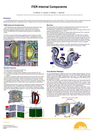
VLT Research Highlights ITER Test Blanket Module (TBM). M. Abdou and the ITER-TBM Team. Outline 1. Introduction and TBWG activities 2. Technical planning and costing activity for US ITER-TBM 3. Examples of recent technical progress. VLT Conference Call – January 18, 2006. Introduction.

E N D
VLT Research Highlights ITER Test Blanket Module (TBM) M. Abdou and the ITER-TBM Team Outline 1. Introduction and TBWG activities 2. Technical planning and costing activity for US ITER-TBM 3. Examples of recent technical progress VLT Conference Call – January 18, 2006
Introduction Tritium Breeding Blankets : complex component submitted to very severe working conditions, needed in DEMO, not present in ITER ► ITER is an unique opportunity to perform integrated experiments using Test Blanket Modules (TBMs) ► It is an ITER mission : “ITER should test tritium breeding module concepts that would lead in a future reactor to tritium self-sufficiency, the extraction of high grade heat and electricity production.” (ITER SWG Report to the IC) ITER Test Blanket Working Group: created to coordinate and integrate into ITER the test blanket programs of the Parties ► is formed by members from all six ITER Parties and from ITER Team ► promotes collaboration on R&D among ITER Parties ► makes recommendations on TBM testing time schedule, feasibility, and usefulness
Main TBM Testing Parameters and Objectives Testing Conditions ►in H-H phase: relevant magnetic fields, surface heat fluxes, disruption-induced loads ► in D-T phase: additional relevant neutron flux, volumetric heat, and Tritium production with corresponding T-management capabilities. ► In late D-T, several back-to-back long pulses with defined heat loads have to be ensured. Main TBM test objectives in the H-H phase ► functional tests, e.g. MHD flow and structural integrity during disruptions/VDE ► impact of ferro-magnetic steel ► TBM system operations and RH equipment ► experimental support to TBM safety dossier Main TBM test objectives in D-T phases ►validation of structural integrity predictions under combined and DEMO-relevant loads ► validation of T-breeding predictions and of T- recovery process efficiency and inventories ► validation of thermal performances predictions ► demonstration of systems integral performance
ITER-TBMs Testing Time Schedule • Testing from Day 1 (TBM installed one year before the start of ITER Operation). • During the first 10 years of ITER Operation, there will be four consecutive TBMs corresponding to the four different phases of plasma operation.
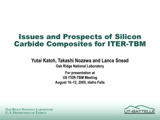
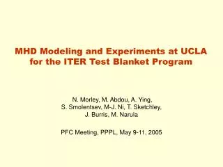
TBM PORTS Shield plug Frame Sample TBM (RF) TBMs Arrangement in ITER and Interfaces ► 3 ITER equatorial ports (opening of 1.75 x 2.2 m2) devoted to TBM testing ► TBMs installed within a water-cooled steel frame (thk. 20 cm), typically half-port size TBMs tests need a whole TBM system TBM The TBMs first wall is recessed of 50 mm and protected with a Be layer vertical horizontal
Summary of TBWG-16 (Beijing, November 2005) • TBWG ITA report was submitted to the ITER PC. • TBWG is to continue in its present format until the end of 2006 with a mandate to establish the framework for the ITER Test Blanket Program. Also, additional focus on i) safety; ii) evaluation of needed resources for ITER interfaces. • TBM Safety and Licensing Requirements:The key issues for the TBM safety and licensing approach are: • Organization:- ITER Organization (IO) is the LEGAL entity for ITER, INCLUDING TBMs, • QA: a QA for TBM is essential for final acceptance. Standards have to be close to the IAEA 50SGQ. For TBM on ITER day one, parties should start a QA system in 2009 at the latest; • Meet the licensing deadline with consistent and sufficient inputs. Safety representatives from each Party were nominated to work with the ITER Safety/Licensing Manager. • The Parties are to present agreed-upon collaborations on specific items from at least two Parties during the next TBWG meetings. • Date of the next meeting is April 4-6, 2006, at the ITER Joint Working Site in CEA/Cadarache (France).
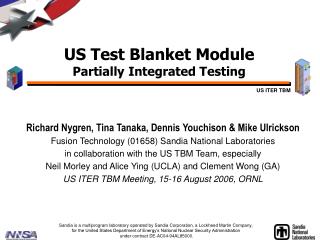
US Selected TBM Concepts • The Dual-Coolant Pb-17Li Liquid Breeder Blanket concept with self-cooled Pb-Li breeding zone and flow channel inserts (FCIs) as MHD and thermal insulator • Innovative concept that provides “pathway” to higher outlettemperature/higher thermal efficiency while using ferritic steel. • US lead role in collaboration with other parties (most parties are interested in Pb-Li as a liquid breeder, especially EU and China). • Plan an independent TBM that will occupy half an ITER test port with corresponding ancillary equipment. • The Helium-Cooled Solid Breeder Blanket concept with ferritic steel structure and beryllium neutron multiplier, but without an independent TBM • Support EU and Japan efforts using their TBM structure & ancillary equipment • Contribute only unit cell /submodule test articles that focus on particular technical issues Cutaway of US DCLL TBM Module HCCB Submodule Conceptual Design as of Jan. 2006
A Detailed TBM Planning and Costing Activity for the US TBM Program is underway – as requested by DOE • Planning is for the US Reference Scenarios: • DCLL TBM with PbLi exit temperature of 470ºC and a series of TBM that occupy half a port. • HCCB submodule that has a size of 1/3 of one-half port in cooperation with the EU or Japan • Detailed planning and cost is for a 10 year period between now and the shipment of the TBM deliverables in 2015 for DAY ONE ITER operation. • The cost is the total cost for the TBM project including R&D, design, engineering, fabrication, qualification, etc., as well as the cost of interface with ITER and other parties. • The R&D Cost includes all costs related to the Reference Scenarios that occur within the next 10 year period whether they are related to the first (Day ONE) Test Articles or subsequent test articles. • Cost of the deliverables includes only the cost of the First Test Article and associated equipment (See Project Deliverables slide).
US ITER TBM Costing Activity Milestones • 12-Aug-05 Costing Activity Initiated • 31-Aug-05 WBS established for Level 6 and lower Responsible persons for Level 6 and lower assigned • 7-Sep-05 WBS for Level 6 and lower revised • 9-Sep-05 Conceptual design summaries for DCLL and HCCB issued • 6-Oct-05 Initial schedule and base cost estimate for WBS level 6 of DCLL and HCCB • 27-Oct-05 Initial schedule and base cost estimate for engineering design, procurement/fabrication, and ancillary equipment • 7-Nov-05 R&D decision criteria established • 30-Nov-05 Complete revised schedule and cost estimate for WBS level 6 and lower (include contingency factor) • 12-14 Dec-05 “Physical” Meeting (all information about costing will be presented and discussed) • 16-Dec-05 R&D priorities finalized • 13-Jan-06 Initial Draft Costing Activity Report Due • 20-Feb-06 Complete Draft of Final Costing Activity Report • 7-8 Mar-06 Physical meeting (internal review of draft report) Date may change • 10-Mar-06 Complete incorporating comments into the Report • 17-Mar-06 Send Final TBM Cost Estimate Report to DOE • 28-Mar-06 “External” review
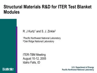
Summary of Technical Planning and Costing Activity • Defined US TBM objectives and deliverables • Developed WBS using US ITER Project Methodology • Selected US TBM concepts • Developed TBM designs, reference scenarios, testing strategy and schedule consistent with ITER operations and constraints • Performed design and analysis for US concepts. Also identified technical issues. • Developed R&D requirements based on TBM technical issues • Developed system of priorities (cost/risk/benefit) • Identified potential international collaborations • Developed schedule for R&D, engineering design, prototype tests, and fabrication • Estimated costs for each WBS element • What remains to be done: • Establishing cost ranges (e.g. based on risk, international collaboration) • Issue draft report for comments
Examples ofTBM Technical Research Underway in the VLT • LM-MHD model development and experiments • Pebble bed thermomechanics model development and experiments • TBM analysis: thermofluid MHD, structural, electromagnetic, tritium permeation, nuclear, accident scenario and thermalhydraulic. • SiC/SiC FCI property measurements, fabrication routes, compatibility with PbLi, irradiation of constituent matrix and fibers • Ferritic steel irradiation, property characterization, and assessment of fabrication and joining procedures
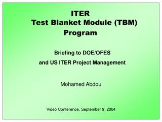
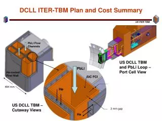
MHD flow and heat transfer issues strongly affect DCLL blanket feasibility, material requirements and TBM design • Example: Velocity profile dependence on location of pressure equalization slot in SiC/SiC flow channel insert with = 20 S/m. 2D Simulation. • Top image, slot on wall perpendicular to magnetic field (new baseline orientation) • Bottom image slot on wall parallel to magnetic field (previous baseline) • Continuing work in LM-MHD for the US DCLL TBM • Models for MHD turbulence and natural convection effects • 3D effects: flow development, pressure distribution, flow distribution • Design of Fundamental Experiments: manifold effects on flow distribution and LM flow and heat transfer with SiC/SiC FCIs B B
Basic properties of SiC/SiC Flow Channel Inserts closely coupled to MHD performance 2D SiC composite,in-plane Monolithic SiC DCLL TBM Target 2D SiC composite,transverse • MHD effects are highly sensitive to the transverse electrical conductivity of the SiC/SiC FCI, but no data previously available in this transverse direction • Data for in-plane of typical fusion grade 2D-SiC/SiC shows relatively high values ~500 S/M, likely due to highly conducting carbon inter-phase • New measurements on same material shows SIGNIFICANTLY lower – 2 to 3 orders lower at 500C – compared to in-plane value • anisotropy of the CVI-deposition process • series contact resistance of woven fabric layers • results must be confirmed • Ideal thermal conductivity (1-2 W/mK) still a serious challenge Preliminary DC electrical conductivity data for 2D-Nic S/CVI-SiC composite. Measurements were made in both argon-3% H2 or dry Ar. Vacuum-evaporated Au-electrodes on disc faces.
LM-MHD research attracting interest of larger scientific community • Recent visits and visitors to discuss collaborations on applications in fusion, electromagnetic processing of materials, and astrophysics • Rene Moreau, Grenoble , 2D turbulence, natural/mixed convection • Oleg Zikanov, University of Michigan, LES and DNS models of MHD turbulence • Parvis Moin, Stanford, new LES turbulence models for MHD turbulence • Hantao Ji, PPPL, free surface LM flows and waves Comparison of zero-equation turbulence model with the experimental data from Grenoble MATUR experiment –model developed by UCLA in collaboration with Rene Moreau
Recent Progress on Pebble Bed Thermomechanics Simulation DEM simulations show that size distribution of a pebble bed can impact bed stiffness and subsequent bed thermomechanical state after a stress relaxation • Simulation results based on discrete element method presented at CBBI-13 has generated considerable interest and requests for help with existing EU in-pile pebble bed tests. • Further experimental study and modeling development of pebble bed thermo-mechanical are necessary to help ITER TBM design. A new IEA task is being defined. • CBBI-13, hosted by UCLA in conjunction with ICFRM, had 27 participants and 21 presentations available at http://www.fusion.ucla.edu/cbbi13/. Color reflects contact stress level of the particle Red: high Blue: low Bed with range of particle size (0.5 to 1.5 mm) A single size (1 mm) pebble bed