Download

1 / 103
1.42k likes | 2.08k Views
Functional Hardware Verification. Introduction to Constrained Random Coverage Driven Verification. Agenda. Introduction (45 min) Coverage (22.5 min) Planning (22.5 min) Testbench structure – UVM (80 min) Other aspects of verification: GLS, Formal, Mixed signal, Low power (10 min).

E N D
Functional HardwareVerification Introduction to Constrained Random Coverage Driven Verification
Agenda • Introduction (45 min) • Coverage (22.5 min) • Planning (22.5 min) • Testbench structure – UVM (80 min) • Other aspects of verification: GLS, Formal, Mixed signal, Low power (10 min)
Directed vs. Random Introduction
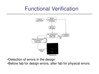
What is Functional Verification • Functional verification is the task of verifying that the logic design conforms to specification. • Functional verification attempts to answer the question: "Does this proposed design do what is intended?"
Why is Verification Important • The estimated mean time required for IP verification is 70% of the overall IP development time.Design process time is only 30%
Directed Approach • Imagine verifying a car using directed method • Requirement: Fuse will not blow under any normal operation • Scenario 1: Accelerate to 50 km/h, put in the Barry White CD, and turn on the windshield wipers
Directed Approach • Imagine verifying a car using directed method • Requirement: Fuse will not blow under any normal operation • Scenario 714: Accelerate to 60 km/h, roll down the window, and turn on the left turn signal
Concurrency Challenge • A purely directed test methodology does not scale. • Imagine writing a directed test for this scenario!
Concurrency Challenge • TBD: Picture of UART IP, with explanation of directed test and random test
Directed Testing • Verification engineer: • Defines DUT states to be tested based on spec behavior and corner cases • Writes directed test to verify each item in Test Plan Significant manual effort to write all the tests! Lots of work required to verify each goal. Poor coverage of non-goal scenarios … Especially the cases you didn’t “think of”
Directed Test Environment • Composition of a directed test • Directed tests each contain stimulus, but each requires more than that… • Checks are typically embedded into the tests to verify correct behavior (usually specific to that test scenario) • Reusability and maintenance • Tests can become quite complex and difficult to understand • Since the checking is distributed throughout the test suite, it is a lot of maintenance to keep checks updated • It is usually difficult or impossible to reuse the tests across projects or from module to system level
Constrained Random Coverage Driven Verification • Verification engineer • Defines DUT states to be tested based on spec behavior (the function to be implemented)and corner cases (edge values and function discontinuities) • Focus moves to reaching goal areas (creative),versus execution of test lists (brute force) Non-goal state Constrained-random stimulus generation explores goal areas (& beyond)Stimuli are automatically generated, based on the constraints specified by VE Coverage reports which goals have been exercised and which need attention Self-Checking ensures proper DUT response
Coverage Driven Environment • Composition of a coverage driven environment • Reusable stimulus sequences developed with “constrained random” generation • Running unique seeds allows the environment to exercise different functionality • Monitors independently watch the environment • Independent checks ensure correct behavior • Independent coverage points indicate which functionality has been exercised
1 3 CRCDV test approach 2
Where Are the Major Differences? • Stim… gen……. • Mon……. and che….. • Cov….. Collection What is the Major Benefit? Coverage Collection vs. Test Vector Generation
Where Are the Major Differences? • Stimuli generation • Monitoring and checking • Coverage collection
Existing Technologies • Languages: e + System Verilog, C/C++, SystemC • Methodologies: eRM+ UVM • Tools: Cadence Incisive + Mentor Questa, Synopsys VCS…
When is verification finished? COVERAGE
What is Coverage? • "What doesn't get measured might not get done.“ • To answer the question “Are we done?” we need to answer: • Were all the design features and requirements (functions) identified in the testplan verified? • Were there lines of code or structures (code) in the design model that were never exercised? • Coverage is a simulation metric we use to measure verification completeness.
What is Coverage? (cont’d) • Once we have a measure of coveragewe might ask some more questions: • When we tested the feature X, did we ever test the feature Y at the exact same time? • Has our verification progress stalled for some unexpected reason? • Are there tests that we could eliminateto speed up our regression suiteand still achieve our coverage goals? • Coverage is a simulation metric we use to measure verification progress and completeness.
Kinds of Coverage • Classification by: • the method (explicit vs. implicit) • the source (specification vs. implementation) • Two forms of coverage are used in industry today: • Code Coverage (Implicit coverage): Inherited from the design • Functional Coverage/Assertion Coverage (Explicit coverage): Made by VE
Code Coverage (remember: implicit) • Code coverage is a measurement of structureswithin the source codethat have been activated during simulation. • Benefits: • It is implicit, so it is automatically generated with little effort • Limitations: • The testbench must generate proper input stimulus to activate a design error • The testbench must generate proper input stimulus to propagate all effects resulting from the design error to an output port • The testbench must contain a monitor that can detect the design error • Even with 100% of code coverage, there could be functionality defined in the specification that was never tested
Types of Code CoverageSupported by Most Tools,in the Raising Level of Sophistication • Toggle coverage - measure the number of times each bit of a register or wire has toggled. Good for connectivity checking. • Block coverage is a variant on the statement coverage which identifies whether a block of code has been executed or not. Good for module verification. • Line coverage - which lines of source code have been executed. • Statement coverage - which statements within our source code have been executed. • Expression coverage (or condition coverage) – - has each condition evaluated both to true and false.Good for exhaustive verification. • Branch coverage – have Boolean expressions in control structures (if, case, while, repeat, forever, for and loop statements) evaluated to both true and false.
Code Coverage Flow • It is best to wait until the RTL implementation is close to complete,before seriously starting to gather and analyzecode coverage results. • Once the results are available, coverage holes are analyzed. • Coverage holes can be due to one of the following reasons: • Missing input stimulusrequired to activate the uncovered code • A bug in the design (or testbench)that is preventing the input stimulus from activating the uncovered code • Unused code for certain IP configurationsor expected unreachable code during normal operating conditions
Functional Coverage (remember: explicit) • Functional coverage helps us answer the question:Have all specified functional requirements been implemented,and then exercised during simulation? • Benefits are defined in coverage definition: • It helps us measure verification progress and completeness • Limitation is that it is explicit, which means it is required to: • Identify the functionality or design intent that you want to measure • Implementing the machinery to measure the functionality or design intent
Types of Functional Coverage • Cover Groupsconsists of state values observed on buses,grouping of interface control signals, as well as register.The values that are being measured occur at a single explicitly or implicitly sampled point in time. • Cover Properties/Assertionsmeasure temporal relationships between sequences of events • Definitions! • Assertion: Statement that proves a fact • Property: Coverage point of view property
Cover Groups vs. Cover Properties/Assertions Example of a cover group: Have we exercised both, Read and Write commands? Example of a cover property: Have we exercised the commandin which the EN signal is delayed, after the SEL signal, for 3 clock cycles?
Functional Coverage Flow • The typical flow is: • Create a functional coverage model • Run simulation to capture and record coverage metrics • Report and analyze the coverage results • Coverage holes have to be minimized;can be due to one of the following reasons: • Missing input stimulus (required to activate the uncovered code),because the VE missed to specify properly:(a) the related functionality, (b) the related edge condition;typical error: over constraining! • A bug in the design (or testbench) that is preventing the input stimulusfrom activating the uncovered code, e.g., existence of unreachable points • Unused functionality for certain IP configurations orexpected unreachable functionality during normal operating conditions,e.g., existence of unreachable code
First thing first planning
Planning • What shall we cover: • Black box vs. white box verification • Cycle accuracy problem • Why is the plan important • What it needs to include • How to create it • What is executable plan
Black Box Verification • In this approach, the DUT is treated as a black box,i.e., only through its boundary. • Benefits: • DUT is verified realistically - as it will be used in the actual system • Testbench can be reused at system level • Limitations: • Reference model needs to be developed • Some scenarios can be time consuming or impossible to verify
White Box Verification • In this approach, the DUT is treated as a white box,i.e., internal signals of DUT are used for additional checkers, coverage, or in a reference model to predict the output. • Benefits: • Easy implementation • Limitations: • Not reusable • Depends on design, so the VE may repeat the same error
Cycle Accuracy Problem • How do we predict the order of packets? • This is the Cycle Accuracy problem. • The verification can not predict accuratelywhich one of the above will happen after the HW is implemented • The solution: • Make your testbench robust enough to be insensitive to cycle accuracy. • Use the white box approach
Why is Planning Important • We already said that the verification accounts for approx. 70% of development time. • Good planning is the best chance we have to shorten that time.
What is Contained in the Verification Plan • Architecture of the testbench • Strategy definition: • Language (SV, e,…) • Which components will be developedand which will be reused • Completeness definition(functional and code coverage targets) • List of tests • Functional coverage definition • List of Checkers • List of features (requirements)
Spec to Plan • Excerpt from the UART functional spec:“The core implements the APB SoC bus interface for communication with the system. The core implements UART serial transmitter and receiver. The core requires one interrupt. TX FIFO of size 16 with programmable threshold is implemented as data buffer on TX path. RX FIFO of size 16 with programmable threshold is implemented on RX path. The block diagram of the core is given below. ”
Spec to Plan (cont’d) • Excerpt from the verification plan(obtained after the functional spec is mapped into the verification plan): Note: Directed method is still useful for specific features
Executable Plan • Executable verification plan is the logical next step • It directly links requirements from the plan with the actual metrics from the testbench:code coverage, functional coverage, properties/assertions, tests • Verification progress is then tracked automatically.
SystemVerilog • SystemVerilog is a combined Hardware Description Language and Hardware Verification Language based on extensions to Verilog • Key verification extensions: • New data types (strings, dynamic arrays, associative arrays, queues) • Classes • Constrained random generation • Assertions • Coverage
What is UVM? • UVM is the Universal Verification Methodology • A methodology and a library that codifies the best practices for efficient and exhaustive verification • A complete, proven solution • Proven solution, with a success record and large community of users with methodology knowledge and commitment • Well-thought-out solution for a wide variety of verification challenges • Open • Standard supported by all major EDA providers • Enables reuse of verification environments • Verification IP can dramatically speed-up delivery and improve quality
UVM and Coverage Driven Verification • Coverage-driven verification(CDV) combines the following aspects to significantly reduce the time spent verifying a design • Automatic stimulus generation • Self-checking testbenches • Coverage metrics • From the UVM point of view: Why CDV? • Eliminate the effort and time to write hundreds of tests • Ensure thorough verification using upfront goal settings • UVM provides the framework to achieve CDV
Detailed Verification Environment Each purple block corresponds to one System Verilog class.