Download
1 / 1
10 likes | 143 Views
Wum / Menchum Bridge Project Cristelle Tardy 1 , Wes Lukridge 1 , and Juan Urena 1 ; Advisors: Dr. Vedrana Krstic 1 , Dr. Nabil Al-Omaishi 1 1 Department of Civil Engineering, The College of New Jersey, Ewing, NJ. Results

E N D
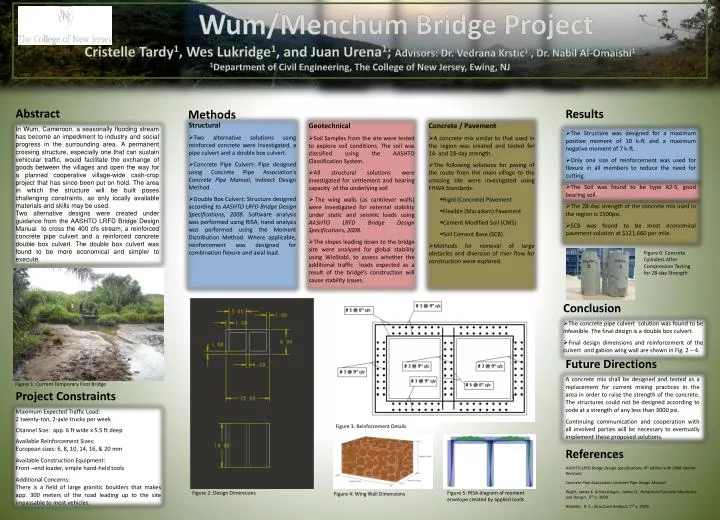
Wum/Menchum Bridge Project Cristelle Tardy1, Wes Lukridge1, and Juan Urena1; Advisors: Dr. VedranaKrstic1 , Dr. Nabil Al-Omaishi1 1Department of Civil Engineering, The College of New Jersey, Ewing, NJ • Results • The Structure was designed for a maximum positive moment of 10 k-ft and a maximum negative moment of 7 k-ft. • Only one size of reinforcement was used for flexure in all members to reduce the need for cutting. • The Soil was found to be type A2-5, good bearing soil. • The 28-day strength of the concrete mix used in the region is 1500psi. • SCB was found to be most economical pavement solution at $121,660 per mile. Abstract In Wum, Cameroon, a seasonally flooding stream has become an impediment to industry and social progress in the surrounding area. A permanent crossing structure, especially one that can sustain vehicular traffic, would facilitate the exchange of goods between the villages and open the way for a planned cooperative village-wide cash-crop project that has since been put on hold. The area in which the structure will be built poses challenging constraints, as only locally available materials and skills may be used. Two alternative designs were created under guidance from the AASHTO LRFD Bridge Design Manual to cross the 400 cfs stream, a reinforced concrete pipe culvert and a reinforced concrete double box culvert. The double box culvert was found to be more economical and simpler to execute. Methods • Structural • Two alternative solutions using reinforced concrete were investigated, a pipe culvert and a double box culvert. • Concrete Pipe Culvert: Pipe designed using Concrete Pipe Association’s Concrete Pipe Manual, Indirect Design Method. • Double Box Culvert: Structure designed according to AASHTO LRFD Bridge Design Specifications, 2008. Software analysis was performed using RISA, hand analysis was performed using the Moment Distribution Method. Where applicable, reinforcement was designed for combination flexure and axial load. • Geotechnical • Soil Samples from the site were tested to explore soil conditions. The soil was classified using the AASHTO Classification System. • All structural solutions were investigated for settlement and bearing capacity of the underlying soil • The wing walls (as cantilever walls) were investigated for external stability under static and seismic loads using AASHTO LRFD Bridge Design Specifications, 2008. • The slopes leading down to the bridge site were analyzed for global stability using WinStabl, to assess whether the additional traffic loads expected as a result of the bridge’s construction will cause stability issues. • Concrete / Pavement • A concrete mix similar to that used in the region was created and tested for 14- and 28-day strength. • The following solutions for paving of the route from the main village to the crossing site were investigated using FHWA Standards: • Rigid (Concrete) Pavement • Flexible (Macadam) Pavement • Cement Modified Soil (CMS) • Soil Cement Base (SCB) • Methods for removal of large obstacles and diversion of river flow for construction were explored. Figure 6: Concrete Cylinders After Compression Testing for 28-day Strength • Conclusion • The concrete pipe culvert solution was found to be infeasible. The final design is a double box culvert. • Final design dimensions and reinforcement of the culvert and gabion wing wall are shown in Fig. 2 – 4. Future Directions A concrete mix shall be designed and tested as a replacement for current mixing practices in the area in order to raise the strength of the concrete. The structures could not be designed according to code at a strength of any less than 3000 psi. Continuing communication and cooperation with all involved parties will be necessary to eventually implement these proposed solutions. Figure 1: Current Temporary Foot Bridge Project Constraints Maximum Expected Traffic Load: 2 twenty-ton, 2-axle trucks per week Channel Size: app. 6 ft wide x 5.5 ft deep Available Reinforcement Sizes: European sizes: 6, 8, 10, 14, 16, & 20 mm Available Construction Equipment: Front –end loader, simple hand-held tools Additional Concerns: There is a field of large granitic boulders that makes app. 300 meters of the road leading up to the site impassable to most vehicles. Figure 3: Reinforcement Details References AASHTO LRFD Bridge Design Specifications, 4th edition with 2008 Interim Revisions Concrete Pipe Association Concrete Pipe Design Manual Wight, James K. & MacGregor,, James G.; Reinforced Concrete Mechanics and Design, 5th e. 2009 Hibbeler, R. C.; Structural Analysis, 7th e. 2009 Figure 2: Design Dimensions Figure 5: RISA diagram of moment envelope created by applied loads Figure 4: Wing Wall Dimensions