Download
1 / 27
280 likes | 464 Views
The G & R HT-1000A and HT-2000A Hand-Held Hardness Testers are advanced instruments distinguished by their friendly operation, durability, small size, high precision, and wide measuring range. Checkout PDF to know more. Visit us : http://grhardnesstester.com/

E N D
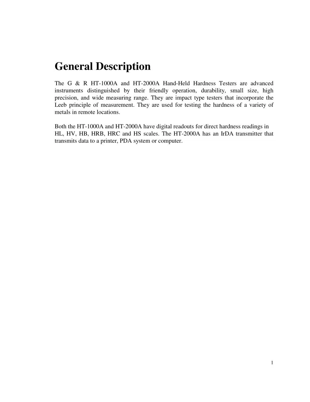
General Description The G & R HT-1000A and HT-2000A Hand-Held Hardness Testers are advanced instruments distinguished by their friendly operation, durability, small size, high precision, and wide measuring range. They are impact type testers that incorporate the Leeb principle of measurement. They are used for testing the hardness of a variety of metals in remote locations. Both the HT-1000A and HT-2000A have digital readouts for direct hardness readings in HL, HV, HB, HRB, HRC and HS scales. The HT-2000A has an IrDA transmitter that transmits data to a printer, PDA system or computer. 1
Contents Chapter Page 1 Technical Specifications 3 2 Check Package 5 3 Functional Description 6 4 Pre-Treatment of the Workpiece To Be Tested 7 5 Basic Operations 9 6 Additional Operations 7 Hardness Tester Maintenance and Repair 21 8 Leeb Measurement and Application 23 9 Constructing Special Comparative Curves 25 18 2
1. Technical Specifications Testing Range: 200-900 HL (Leeb Value) Converted Hardness Scales: HB, HV, HRB, HRC, HS Accuracy and Variation: +/- 4 HL value or +/- 0.5% (based on the average of five measurements around 800HL) Testing Direction: Any direction Steel Ultimate Tensile Strength (UTS): Kgf/mm² (38 to 267 Kgf/mm²) Tons/in² (23 to 135 Tons/in²) Lbs/in² (54 to 382 Lbs/in²) Temperature: Operating Temperature: 14°F to 104°F (-10°C to 40°C) Storage Temperature: - 4°F to 122°F (-20°C to 50°C) Data Storage: Automatic recording and storing of up to 500 test results including readings, time, test material, test hardness scale, and test direction. (HT-1000A stores up to 10 testresults.) Clock: Real time and date with a ten years calendar. Power Supply: Tester: Two 3 V Lithium Batteries (CR2330) Printer: Li-Lon rechargeable battery Battery Life: Tester: Work life 80 hours continuous (Up to 4000 tests) Sleeping life 2 years continuous Printer: More than 10000 lines per full charge Tester Weight: 4.25 oz (120g) Tester Dimensions: 6.5” x 1.1” x 1.1” (165mm x 28mm x 28mm) 3
Material Hardness Measuring and Converting Ranges: Standard Hardness Scales Workpiece/ Sample Under Test ( HL ) ( HV ) Steel/Cast Steel ( ST ) 300 - 900 80 - 940 Alloy Tool Steel ( AS ) 300 - 840 80 - 900 Stainless Steel or Refractory Steel ( SS ) Bearing Steel ( GS ) 500-880 80 - 800 Gray Cast Iron ( GC ) 360 - 660 Nodular Cast Iron ( NC ) 400 - 660 Aluminum Alloys ( AL ) 200 - 560 32 - 190 Brass ( BS ) 200 - 560 45 - 200 Bronze ( BZ ) 300 - 700 Copper ( CU ) 200 - 420 50 - 130 Table 1.1 Notes: The above table shows the valid hardness ranges for typical materials. A test outside the specified range is invalid and the display screen will indicate an “E” (Error). Errors are normally caused by setting the tester for a different material than that being tested. If the hardness of a material is not in the range given by the table, the hardness is not valid and will produce an error. Leeb Vickers Brinell ( HB ) 80 – 650 (F=30D²) Rockwell B ( HRB ) 38.4 -99.5 Rockwell C ( HRC ) 20 - 68 20.4 - 67 20 - 63 Shore D ( HS ) 32.5 -99.5 300 - 800 85 - 800 85 - 670 (F=30D²) 46.5 - 100 20 – 68.8 32.5 -99.0 93 - 340 (F=30D²) 130 -390 (F=30D²) 30 -160 (F=10D²) 40 - 180 (F=10D²) 60 –290 (F=10D²) 45 -120 (F=10D²) 27 - 91 12 - 94 4 - 72 4
2. Check Package HT-1000A Package Includes: HT-1000A Hardness Tester Standard Test Block Support Ring .79” (20 mm) Support Ring .53” (13.5 mm) CR-2330 Lithium Batteries (2) Plastic Carrying Case Tube Cleaning Brush Operating Instructions HT-2000A Package Includes: HT-2000A Hardness Tester PORTI-S Micro printer A/C Adaptor Standard Test Block Support Ring .79” (20 mm) Support Ring .53” (13.5 mm) CR-2330 Lithium Batteries (2) Plastic Carrying Case Tube Cleaning Brush Operating Instructions Optional Equipment Impact body with diamond test tip for measurements of extremely high hardness (up to 1200 HV hardness range). Example, the cold work tool steel with carbide inclusions. Impact body with long test tip for extremely confined spaces at the base of grooves. Set of 12 Special Support Rings for testing curved and uneven surfaces. 5
3. Functional Description Figure 3.1 illustrates the HT-1000A/HT-2000A hardness testers. 2 4 3 1 9 10 11 8 7 5 6 Figure 3.1 Support Ring I/O Key Key Load Tube Release Button Press the I/O key to power ON/OFF. Pressing this key will switch the power from OFF to ON or ON to OFF. When the tester is turned OFF, it enters a sleep mode: the memory is saved and the timer still runs. When the power is turned back ON, the tester will automatically go to the last test results with the previous settings intact for ease of operation. Note: To prolong battery life, the tester will automatically enter sleep mode if the tester has been idle for approximately one minute. SET Key Key LCD Monitor 11 PR Key Key IrDA Transmitter 3 1 2 6 4 5 7 8 9 10 6
4. Pre-Treatment of the Workpiece to be Tested Selection of the workpiece to be tested and preparation of its surface prior to testing will help insure accuracy. Weight Requirement To achieve correct test results, select thick, heavy, and solid workpieces for testing whenever possible. The surface area where the impact body strikes should have an even hardness. A solid workpiece that weighs more than 11lbs. (5Kg) can be tested on directly with the HT-1000A/HT-2000A hardness testers. A workpiece that weighs 6 to 11lbs. (3 to 5Kg) should be fixed to a bearing or support weighing over 11lbs (5kg) to avoid bending, deformation, and displacement during testing. A workpiece that weighs less than 4 lbs. (2Kg) should be secured to a workbench or a stable support. The surface between the workpiece and the support must be hard, clean, and smooth. To secure the workpiece, apply petroleum jelly or yellow grease to the adjoining surfaces of the workpiece and support, press the workpiece firmly onto the support, and eliminate any air between the two surfaces by moving the workpiece back and forth. Roughness Requirement To eliminate measurement errors which could result from the roughness of the test surface, the surface should be polished so that a metallic luster appears. The roughness (Ra) of the surface must be limited to ≤ 2µ µ µ µm. Note that the rougher the surface of the workpiece, the lower the hardness test results. Cleanliness Requirements To ensure test accuracy, the test surface of the workpiece must be clean and free of any oil stains, rust, and remains from electro-plating or paint. Stability Requirements To avoid displacement during testing, the workpiece should be firmly fixed with its test surface perpendicular to the impact direction. Due to the impact of the 7
Impact Body, the test area may deform or vibrate, even for some workpieces with suitable weight and thickness. The tested hardness may be lower than normal. This is especially true for workpieces such as a large plate, a long bar or a rod, and workpieces with a curved surface. Some testing recommendations for these workpieces are shown in figure 4.1 Figure 4.1. Workpieces with Curved Surfaces The larger the curvature of the workpiece’s surface, the easier the testing operation. Under normal conditions, testing can be done directly with the standard support ring to a curvature with radius of 1 3/16” (30mm) or longer. For a workpiece with a radius of less than 1 3/16” (30mm), a special support ring should be used for testing. Note: A set of 12 rings is available for testing curved and uneven surfaces. 8
5. Basic Operations Powering On Press the I/O key to turn on power. The LCD monitor will show the last test results: Figure 5.1 Select operating parameters. 1. Press the SET key to start and set up a new test. You will now select the operating parameters. The LCD monitor will prompt for a number of test results in the test group: Figure 5.2 Press the key or the key to adjust from 1 to 10. After you have selected a value, press the key to select a testing material. 2. The LCD monitor will now prompt for the workpiece material. Press the key or the key to adjust from ST, AS, SS, GS, GC, NC, AL, BS, BZ or CU. The LCD monitor will display: 9
Figure 5.3 ST AS SS GS GC Carbon Steel Alloy Steel Stainless Steel Bear Steel Gray Cast Iron NC AL BS BZ CU Nodular Cast Iron Aluminum Brass Bronze Copper Press the key again to select a testing scale. 3. The LCD monitor will now prompt for a testing scale. Press the key or the key to adjust from HL, HV, HB, RB, RC or HS. The LCD monitor will display: Figure 5.4 HL HV HB RB RC HS Leeb Vickers Brinell Rockwell B Rockwell C Shore Press the key again to select a testing direction. 4. The LCD monitor will now prompt for a testing direction. Press the key or the key to adjust from ?,?,?,? or?. The LCD monitor will display: 10
Figure 5.5 ? ? ? ?? ? ? ?? Vertically Down 45° Down Horizontal 45° Up Vertically Up 2. If any parameters need to be changed, press the key again to select a number of test results in the test group and start over from step 1. Otherwise, press the SET key to end selection of the operating parameters. The HT-1000A will clear the memory while the HT-2000A will begin to store new test results, and display: Figure 5.6 Testing 1. Push the Loading Tube towards the support ring until it is engaged. Then, while still holding on to the loading tube, slowly return it to its original position. Caution: Returning the Loading Tube back to its original position too quickly may damage the tester’s parts. ALWAYS hold onto the Loading Tube and slowly guide it back in a controlled fashion. 2. Holding the tester between your thumb and index finger, hold the tester against the workpiece. 3. Keeping the tester steady, press the Tester Release Button.(See figure 5.7) ? ? ?? ? ? ?? ? ? ? 11
THE TESTING RELEASE BUTTON SHOULD BE PRESSED SLOWLY AND LIGHTLY. 4. After two seconds, the test results are displayed and stored in the tester’s memory. The LCD monitor will display: Figure 5.8 Test results 5. If the test results are outside the ranges listed in Table 1.1, the screen will display: Figure 5.9 Error result 12
Errors are normally caused by not configuring the tester for the correct test material. If the test results are incorrect, they can be deleted using the procedure “Search & Delete Tested Results ” on p.17. Change window Results can be displayed in three possible windows: maximum and minimum values, average value of the group, or UTS value. To select a window, press the key to cycle through the different results. Average Value Leeb Value Minimum Value Maximum Value Converted HV value UTS kgf/mm value UTS type Impact body type Material Figure 5.10 Notes: 1. When LD or DD is selected as the impact body, the monitor will display LD. For DL, it will display DL. See P. 19: “Additional Operations” 2. When the UTS standard Kgf/mm² is selected, the monitor will display KGM. For KLbs/in², it will display KSI. For Tons/in², it will display TNI. 13
Transmit Data to Printer or PDA system using IrDA (HT-2000A Only) Press the PR key to start transmitting data. The LCD window will display: Figure 5.11 1. To print the test results, press the PR key again. The LCD window will display the current test group number. Press the key or the key to select the group number you want to print. Figure 5.12 Turn on your printer and align the IrDA window of the printer with the IrDA window of the HT-2000A tester. Then press the PR key again to send the data to the printer, and the LCD monitor will display following: Figure 5.13 14
2. To transmit the data to a Palm PDA system or PC system, press the SET key and the LCD window will display the current test group number. Press the key or the key to select the group number you want to transmit. Figure 5.14 Turn on the PDA system or PC system and align the HT-2000A IrDA window with the PDA or PC system’s IrDA window. Press the PR key again to start sending the data. During transmission, the LCD monitor will display: Figure 5.15 If the receiving system (printer, PDA, or PC) successfully receives the data, then it outputs the following data, and the HT-2000A hardness tester will return to the previous window. Testing Group 02 Testing Time 09/25/06 08:36 PM Material: ST Angle: 000 No. HL HV KGM 01 782 636 227 02 782 636 227 03 783 638 228 04 783 638 228 AVE 782 637 227 15
If the HT-2000A hardness tester does not successfully send the data to printer, the LCD monitor will display: Figure 5.16 If the HT-2000A hardness tester does not successfully communicate with the PDA or PC system, the LCD monitor will display: Figure 5.17 After 30 seconds, RH-150 hardness tester will return to previous window. If unsuccessful, the printer or PDA system might be turned off or not within the range fo the IrDA window of the RH-150 hardness tester. Note: the printer is preconfigured for protocol IrDA. If the configuration is changed incorrectly, the printer needs to be reconfigured. Reconfiguration instructions are in the printer user manual. The printer should setup following: Mode Protocol IrDA Baud rate 9600 Hz 8 Data Bit No Parity 1 Stop Bit Density Medium The printer user manual can be downloaded at: http://www.woosimsystems.com 16
Click on the link “Mobile Printers” Then click on the link “PORTI-S30/40” Then download the user manual. The printer configuration is detailed on page 16: “2.5 Setting Operation Mode” Data Memory Management TheHT-1000A hardness tester stores up to 10 test results, including workpiece material, hardness scale and direction. If the number of tests exceeds 10, the tester will delete ALL 10 previous test results. The subsequent tests (starting at the 11th test) are stored and used for the next average hardness calculation. The HT-2000A hardness tester can store up to 500 test results, including workpiece material, hardness scale, direction and testing time and date. The HT-2000A hardness tester divides its memory into 50 sets. Each set stores up to 10 test results. If the number of tests exceeds ten, subsequent tests are stored in the next set and used for the next average hardness calculation. Search & Delete Tested Results 1. Search data in the current test group From the test results, press the key to search and cycle through the test results in the current group. To delete the data onscreen, press the key. The data will be deleted from memory and the LCD monitor will display the last test result. To the results without deleting anything, press the SET key or do another test. The latest test result will be displayed. 2. Delete current test result From the test results, press the key to delete the test result onscreen. Clear All Memory First, start with the power off. While holding down the SET and key,press and hold down the I/O key, then release the SET and key, and finally release the I/O key. All memory is cleared. 17
6. Additional Operations The following are procedures to change the tester’s configuration for impact body (standard impact body or long tip impact body), change the UTS standard, change the date format, set the clock, and adjust the tester offset. First, start with the power off. While holding down the SET and key, press and hold the I/O key, then release the SET and key, and finally release the I/O key. The screen will display Figure 6.1: Select impact body type procedure Press the key to select an impact body. Figure 6.1 When using the standard impact body, select LD. When using the diamond impact body, select DD. When using the long tip impact body, select DL. Press the SET key to continue and select the UTS standard procedure. Procedure for Selecting UTS Standard Press the key and scroll through various UTS standards, see Figure 6.2: Figure 6.2 18
NR KG KS TN No conversion Kgf/mm2 Klbs/in2 Tons/in2 Press the SET key again to continue and set the date format. Set the Date Format and Clock (HT-2000A Only) Press the key to choose between USA (US Month/Day/Year) and European (EU Day/Month/Year) date format, as in Figure 6.3: Figure 6.3 Press the SET key again to continue and set the clock. You can adjust the time to your preferences. Press the key to cycle through and select a parameter YR (year), MH (month), DY (day), AM/PM (hour), and ME (minute). Press the or key to increase or decrease the value for the selected parameter. Figure 6.4 Press the SET key to continue and enter adjust tester offset procedure. 19
Adjust tester offset You can adjust the offset parameter to match the test result of the standard test block to the block’s actual hardness. When the test result is lower than the standard hardness, press the key to increase the offset. When the tester hardness reference is higher than the standard hardness, press the key to decrease the offset number. See figure 6.5. The offset range is from -50 to 50 in Leeb hardness values. Figure 6.5 After finishing adjusting the offset, press the SET key again to finish configuration and save the settings. The tester will enter the test results screen (Fig. 5.6). The HT- 1000A will delete all previous test results. The HT-2000A will store the last results in a set and begin a new set. 20
7. Hardness Tester Maintenance and Repair Tester Storage and Operating Precautions The HT-1000A/HT-2000A testers are precision instruments. When storing or operating the tester, avoid the following: 1. Dropping the tester or subjecting it to shock and sharp impact. 2. Dropping or spilling any oil, grease and/or other liquids onto the tester. 3. Applying any oil, grease and other liquid to the workpiece being tested. 4. An operating environment with heavy dust or gas that can damage to the tester. 5. Material that far exceeds the testable hardness range. Replacing Batteries The battery life is eighty hours. The battery life will vary with the frequency of use. If the monitor displays BATT, the batteries should be replaced following this procedure: 1. Use two, 3V Lithium CR2330 batteries (Panasonic brand batteries recommended). 2. Install batteries in series, both cells’ positive terminals should face the side with the symbol on the battery holder. 3. Voltage levels of the two batteries should be the same. Replace both batteries atthe same time. Caution: After changing batteries in the tester, turn the tester power ON, then OFF to enter sleep mode. Cleaning the Tester The tester’s Guide Tube should be cleaned periodically. Under normal operating conditions it is recommended that cleaning be done after 1,000 tests or after 1–2 months of use, whichever comes first. 21
The Guide Tube should be cleaned using the included brush following this procedure: 1. Unscrew the Tester Support Ring. 2. Remove the Impact Body. 3. Brush the inside of the Guide Tube several times. 4. Clean the Impact Body with alcohol or other “non-oil” based cleaning fluid. 5. Replace the Impact Body (note, the Impact Ball Head should face towards the Support Ring). 6. Replace the Support Ring. Impact Body and Tester Accuracy When results from repeated testing on a standard hardness test block are consistently higher than the actual hardness value, the Impact Body is probably worn. Please contact our Customer Service Department to replace the Impact Body. Note: If problems occur with the tester or any accessories, do not attempt to disassemble or repair the tester. Contact our Customer Service Department for assistance. 22
8. Leeb Measurement and Application Principles of the Leeb Measurement Method were introduced to the hardness testing industry in 1978. Using the quotient of the rebound and impact voltages that are proportional to the rebound and impact velocities on an impact body, the hardness of a workpiece under test can be determined. The harder the surface of the workpiece, the faster the rebound velocity and the larger the test value. The Leeb hardness (L-value) represents a direct hardness measurement for the following materials: steel, cast steel, alloy steel, stainless steel or refractory steel, gray iron, nodular, aluminum, brass, bronze, and copper. Brinell, Rockwell, Vickers and Shore values are determined using static conversion curves. Definition of the Leeb Hardness Test An impact body, i.e. a tungsten-carbide ball of a specified diameter, is projected against the workpiece under test with a given impulse force. At a distance of 0.039”(1 mm) from the surface of the workpiece, both the impact and rebound velocities are measured using the electromagnetic principle where the induced voltages are directly proportional to these velocities. Leeb hardness can be measured electronically and its L-value is defined by: Vb L= (-----)x 1000 Va Where Vb is the rebound velocity of the impact body, and Va is the impact velocity of the impact body. The voltage characteristics of the rebound and impact velocities, as the impact body passes through the induction coil, are shown in figure 11.1 and 11.2. 23
Figure 11.2. 24
9. Constructing Special Comparative Curves Leeb and Other Hardness Comparative Curves for a Typical Workpiece The HT-1000A/HT-2000A hardness testers store Leeb and other hardness comparative curves for ten types of materials. The hardness comparative curves should meet most hardness testing requirements. However, if testing of a special type of material is required, a hardness comparative curve can be constructed for Leeb and other static formats. Guidelines for Selecting and Pre-Testing a Test Sample 1. The type of material for the test sample should match the type of material of the workpiece. 2. Select large and heavy test samples whenever possible. A solid cylinder with a diameter of 3 ½” (90mm) and length 2 3/8” (60mm) is recommended. 3. The surface of the test sample should be treated to meet all the requirements described in “Pre-treatment of the Workpiece Under Test” (page 8). 4. To construct a hardness comparative curve, three test samples of the same material but of different hardness values are selected to find the upper extreme, the lower extreme, and the medium values. Hardness Measurement for Test Samples Select the desired hardness format for the test samples (i.e. Brinell, Vickers, Rockwell B, or Rockwell C), then use the hardness tester to determine the standard Leeb hardness (HL) of the test sample. Measurement requirements are as follows: 1. Test points should be selected on the spiral shown in figure 12.1, additionally, the following requirements must be met: 25
The center of Leeb testing markings on the tested surface should be ≥ 0.12” (3mm). The center of static testing markings on the tested surface should be ≥ 0.4” (10mm). The distance between the center of the Leeb testing marking and the edge of the static testing should be ≥ 0.12” (3mm). The distance between the center of the Leeb marking and the edge of the test sample should be ≥ 0.2” (5mm). 2. Prior to testing the samples, the static hardness tester should be adjusted. The testing block hardness, for adjustment purposes, should be close to the hardness of the workpiece under test. 3. Similar to the static hardness tester, the Leeb hardness tester should also be adjusted prior to testing the samples. 4. During testing, the test sample should be level so the Impact Body is perpendicular to the tested surface. Creating Hardness Comparative Curve for Samples 26
Calculate the average value of the test results obtained from Leeb hardness testing for a specific test sample, (use appropriate test results if the test sample is re-tested), then use this value for plotting. Similarly, the average value of the test results obtained from static hardness testing for the test sample can be used for plotting. Use the static hardness values as the x-axis, and the Leeb values as the y-axis, plot a point for the obtained average values for each test sample on the plotter paper. Repeat plotting for two other points. Connect the three points to construct a smooth curve. Note: The more the points, the smoother the constructed curve. A better comparative curve can be generated with more test samples and more tests. Hardness Comparative Curve for Direction Adjustment In case the surface of the workpiece under test is not perpendicular to the direction of gravity, different test angles can be selected in the testers to compensate for the gravitational effects. With the built-in comparative curves in the micro-controller memory, the hardness tester can automatically adjust the Leeb test results according to the direction of testing and convert the Leeb hardness values to other desired hardness values. 27