Download
1 / 28
280 likes | 500 Views
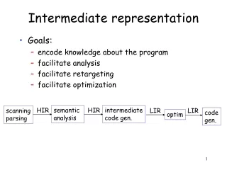
MCLinker Intermediate Representation. Luba Tang 2013/2/24. Agenda. Introduction to Linkers and Loaders Related works The value of MCLinker Intermediate Representation MCLinker Intermediate Representation Module and Input Tree Fragments and Reference Graph MCLinker linking algorithm

E N D
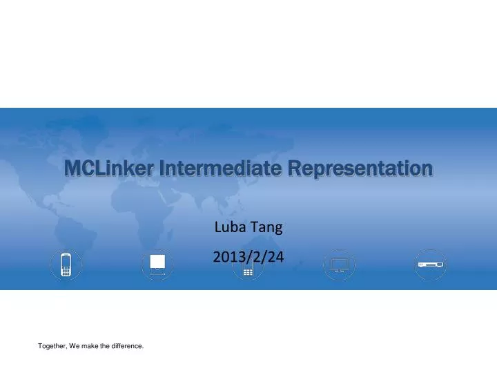
MCLinker Intermediate Representation Luba Tang 2013/2/24
Agenda • Introduction to Linkers and Loaders • Related works • The value of MCLinker Intermediate Representation • MCLinker Intermediate Representation • Module and Input Tree • Fragments and Reference Graph • MCLinker linking algorithm • Normalization • Resolution • Layout • Emit Luba Tang, software architect of MCLinker MediaTek, inc.
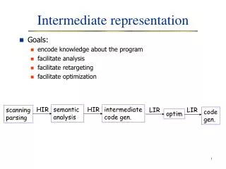
Introduction to MCLinker Intermediate Representation • MCLinker is the first *ELF linker to provide an intermediate representation (IR)for efficient transformation and analysis • MCLinker provides IR on two levels • Linker Command Line Language • Fragment-Reference Graph • Fragment is the basic linking unit, it can be • A section (coarse granularity) • A block of code or instructions (middle granularity) • An individual symbol and its code/data (fine granularity) • MCLinker can trade linking time for the output quality. • The finer granularity, • Fast, smaller program • Longer link time * Nick Kledzik invents the Atom IR in ld64 for MachO. ld64 inspires MCLinker IRs
The Linker Command Line Language • Linker’s command line options is a kind of language • The meaning of a option depends on • their positions • the other potions • Some options have its own grammar • Four categories of the options • Examples • Input files • Attributes of the input files • Linker script options • General options ld /tmp/xxx.o –lpthread ld –as-needed ./yyy.so ld –defsym=cgo13=0x224 ld –L/opt/lib –T ./my.x
The GNU ld Linker • The GNU ld linker is an interpreter ofthe command line language • Processing is recursive. • No clear separation between individual steps • Binary File Descriptor (BFD) is the only IR
The Google gold Linker • The Google gold linker separates linking into two stages • Symbol resolution • Relocation of instructions and data • Although it has separated the linking processes, it does not provide reusable IR for optimization and analysis • The Google gold linker illustrates an efficient linking algorithm • It’s x2 faster than the GNU ld linker • Support multiple threads. Appropriate to cloud computing
MCLinker • MCLinker separates the linking into four distinct stages • Normalization – parse the command line language • Resolution– resolve symbols • Layout– relocate instructions and data • Emission– emit file by various formats • MCLinker provides two level intermediate representation (IR) • The command line language level • The reference graph level
Input Files on The Command Line • An input file can be an object file, an archive, or a linker script • Some input files can be defined multiple times • The result of linking depends on the positions of inputs on the command line. • Weak symbols are first-come-first-served • COMDAT sections are first-come-first-served • Two semantics to read input files • INPUT( file1, file2, file3, ...) • GROUP( archive1, archive2, archive3, ...) • Archives in a group are searched repeatedlyuntil no new undefined references are created $ lda.o–start-groupb.ac.a–end-group d.oe.o
The Input File Tree • We can represent the input files on the command line by a tree structure • Vertices describes input files andgroups on the command line • Object files • Archives • Linker scripts • Entrances of groups • Edges describe the relationships betweenvertices • Positional edges • Inclusive edges • Linkers resolve symbols by DFS and merge sections by BFS • Example $ lda.o–start-groupb.ac.a–end-group d.oe.o
Attributes of Input Files • Attributes change the way that a linker handles the input files • Attributes affect the input files after the attribute options
Attributes in The Input File Tree • Every input has a set of attributes • In the MCLinker implementation,we give every vertex a reference to its attribute set • If two vertices have identical attributes, they can share a common attribute set. • Example $ld./a.o--whole-archive--start-group./b.a ./c.a--end-group--no-whole-archive./d.o ./e.o
Normalization • Transform the command line language into the input file tree • Parse command line options • Recognize input files to build up sub-trees • Merge all sub-trees to a form the input file tree
Steps of Normalization • Step of normalization • Parse the command line options • Recognize archives and linker scripts • Read the linker scripts and archives to create sub-trees • Merge all sub-trees • Example $ ld ./a.o./b.a./c.o
Traverse the Input File Tree • MCLinker provides different iterators for different purposes • For symbol resolution • Depth first search for correctness • For section merging • Breadth first search for cache locality of the output file
Resolution • Transform the input file tree into the reference graph • Resolves symbols • Reads relocation • Builds the reference graph
Symbols and Relocations • A fragment is a block of instruction code or data ina module • A fragment may be • a function, • a label (Basic block), • a 32-bit integer data, and so on. • A defined symbol indicates a fragment • A relocation represents an use-define relationship between two fragments Symbol @a Symbol @bar Module X Module Y define @bar() … add @a, 0x1, 0x2 … @a = global i32 0 … relocation use define
Fragment-Reference Graph (1/2) • A reference is a symbolic linkage between two fragments • A reference is an directed edge from use to define a reference • MCLinker represents the input modulesas a graph structure • Vertices describe the fragmentsof modules • Edges describe the references between two fragments define use use fragment relocation define fragment symbol
Fragment-Reference Graph (2/2) • A Fragment-Reference Graph is a digraph, FRG = (V, E, S, O) • V is a set of fragments • E is a set of references, from use to define • S is a set of define symbols. They are the entrances of the graph • O is a set of exits and explains later. __global __start fragment edge
Symbol Resolution • Determine the topology of the reference graph • Relocation is a plug • Define symbol is a slot • Symbol resolution connects plugs and slots. • Symbols has a set of attributes to help linkers determine the correct topology define Which one? symbol define fragment define use use fragment Undefine symbol relocation define symbol define fragment
Optimizations on the Fragment-Reference Graph • Fragment stripping • Remove unused fragment for shrink code size (Reachability problem) • Traditional linkers strip coarse sections. But MCLinker can strips finer-grained fragments. • The finer granularity, the smaller code size • Branch optimization • Replace high cost branch by low cost branch • Optimizing by change of the relocation type • Low-level inlining • Fragment duplication for TLS optimization and copy relocations
Layout • To serialize the reference graph into a address space • Scan relocations • Layout • Apply relocations
Exits of The Fragment-Reference Graph • A Fragment-Reference Graph is a digraph, FRG = (V, E, S, O) • O is a set of exits. An exit represents a dynamic relocation to GOT. • Represent to access external variables or to call an external function exits the FRG • If the defining fragment is in an external module, then MCLinker will add exits for the references to the outside module. • We have no way to know the memory address of the external module until the load time • We add the Global Offset Table (GOT) for the unknown addresses • We add dynamic relocations for all entries of the GOT • Loader will apply the dynamic relocations and set the correct address in the GOT. • The program use the GOT to accesses the external module indirectly use define __start GOT relocation relocation __global exit
Layout • Layout is a process to finalize the address of fragment and symbols • Sorts FRG=(V, E, S, O) topologically • Assigns addresses to {V, S, O} • Before layout, we must calculate the sizes of all elements of the graph • Relocation scanning • Reserve exits and calculate the sizes of all exits • Undefined global symbol, GOT, and dynamic relocations • *Pre-layout • Calculate the size of all fragments • Calculate the size of all entrances • Global symbols and the hash table * MCLinker follows the Google gold linker’s naming. But pre-layout is opaque and may be renamed.
Apply relocation (1/2) • Adjusts the content of using fragments • Final addresses of symbol is known after layout • Correct use fragment by accessed address Symbol Table define Module Y use … 0x24 @a … add @a , 0x1, 0x2 relocation 0x24
Apply relocation (2/2) • Replaces absolute addresses by PC-related offset if supported by the target • Basic Relocation Formula S – P + A • S: the symbol value • P: the place of the use instruction • A: addend, adjustment (by the instruction format) … @a … add @a , 0x1, 0x2 S S - P P A address space
Optimizations on Layout • Dynamic Prelinking • If the system puts shared libraries at a fixed memory location, we can fill GOT with fixed addresses to avoid symbol look up in the loader • Static Prelinking • If the system puts shared libraries at a fixed memory location, we can directly refer to the fixed addresses without any exits • Symbol Stripping • Strip the undefined symbols which is not a exit
Emission • Emits the module in the output formats • Adds format information • Writes down the IR • In order to improve both cache and page locality, MCLinker collects and performs most file operations in this stage. • MCLinker copies the content in the inputs and applies the resolved reference in this stage.
Conclusion • We’ve introduced MCLinker intermediate representations • The Linker Command Line Language • The Fragment-Reference Graph • We’ve indicated many optimization opportunities in MCLinker IRs.