Download
1 / 36
380 likes | 646 Views
NETW 704. Signaling & Network Control. Signaling System 7. Dr. Eng. Amr T. Abdel-Hamid. Winter 2011. Signaling System 7. SS7/C7 is the protocol suite that is employed globally, across telecommunications networks, to provide signaling.

E N D
NETW 704 Signaling & Network Control Signaling System 7 Dr. Eng. Amr T. Abdel-Hamid Winter 2011
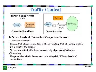
Signaling System 7 • SS7/C7 is the protocol suite that is employed globally, across telecommunications networks, to provide signaling. • It is a packet-switched network, as well as a service platform. Being a signaling protocol, it provides the mechanisms to allow the telecommunication network elements to exchange control information. • SS7/C7 is the key enabler of the public switched telephone network (PSTN), the integrated services digital network (ISDN), intelligent networks (INs), and public land mobile networks (PLMNs).
Signaling System 7 • Each time a cellular phone is powered up, SS7/C7-based transactions identify, authenticate, and register the subscriber. • SS7/C7 network tracks the cellular subscriber to allow call delivery, as well as to allow a call that is already in progress to remain connected, even when the subscriber is mobile. • SS7/C7 is possibly the most important element from a quality of service (QoS) perspective, as perceived by the subscriber.
Impact of SS7 Network Failure • The critical nature of the SS7 network and the potential impact of failures was demonstrated in January 1990 when a failure in the SS7 software of an AT&T switching node rippled through over 100 switching nodes. The failure caused a nine-hour outage, affecting an estimated 60,000 people and costing in excess of 60 million dollars in lost revenue as estimated by AT&T.
Signaling System No. 7-Based Services • Telephone-marketing numbers such as toll-free and freephone • Televoting (mass calling) • Single Directory Number • Supplementary services • Calling name (CNAM) • Local number portability (LNP) • Cellular network mobility management and roaming • Short Message Service (SMS) • Enhanced Messaging Service (EMS)— Ringtone, logo, and cellular game delivery
Signaling System No. 7: The Key to Convergence • SS7/C7 is invested with Internet and other data-centric technologies to enable: • Internet Call Waiting • Internet Calling Name Services • Click-to-Dial Applications • Web-Browser-Based Telecommunication Services • WLAN "Hotspot" Billing • Location-Based Games
Pre-SS7 Systems • CCITT R1 (regional 1) • . • . • C6 (CCITT Signaling System No. 6), also called SS6, was the first system to employ Common Channel Signaling (CCS). • AT&T developed SS7/C7 in 1975, and the International Telegraph and Telephone Consultative Committee (CCITT) adopted it in 1980 as a worldwide standard.
SS7 Network Architecture • The worldwide signaling network has two functionally independent levels: • International • National • SS7 network nodes are called signaling points (SPs). • Each SP is addressed by an integer called a point code (PC): • The international network uses a 14-bit PC. • The national networks also use a 14-bit PC except North America and China, which use an incompatible 24-bit PC.
Signaling Links and Linksets • SPs are connected to each other by signaling links over which signaling takes place. • The bandwidth of a signaling link is normally 64 kilobits per second (kbps). • To provide more bandwidth and/or for redundancy, up to 16 links between two SPs can be used. A group of links between two SP is called a linkset.
Routes and Routesets • SS7 routes are statically provisioned at each SP. There are no mechanisms for route discovery. • A route is defined as a preprovisioned path between source and destination for a particular relation. • All the preprovisioned routes to a particular SP destination are called the routeset.
Node Types • There are three different types of SP: • Signal Transfer Point • Service Switching Point • Service Control Point
Signal Transfer Point • A Signal Transfer Point (STP) is responsible for the transfer of SS7 messages between other SS7 nodes, acting somewhat like a router in an IP network. • An STP is neither the ultimate source nor the destination for most signaling messages. • An STP can exist in one of two forms: • Standalone STP: deployed in "mated" pairs for the purposes of redundancy. Under normal operation, the mated pair shares the load. If one of the STPs fails or isolation occurs because of signaling link failure, the other STP takes the full load until the problem with its mate has been rectified. • Integrated STP (SP with STP): combine the functionality of an SSP and an STP. They are both the source and destination for MTP user traffic. They also can transfer incoming messages to other nodes.
SSP and SCP • Service Switching Point • A Service Switching Point (SSP) is a voice switch that incorporates SS7 functionality. • An SSP can originate and terminate messages, but it cannot transfer them. If a message is received with a point code that does not match the point code of the receiving SSP, the message is discarded. • Service Control Point • A Service Control Point (SCP) acts as an interface between telecommunications databases and the SS7 network. • Telephone companies and other telecommunication service providers employ a number of databases that can be queried for service data for the provision of services.
1. caller goes offhook, dials callee. SSP A decides to route call via SSP B. Assigns idle trunk A-B Example: signaling a POTS call 4. STP X forwards IAM SSP B 3. STP W forwards IAM to STP X 2. SSP A formulates Initial Address Message (IAM), forwards to STP W W Y X A B
5. B determines it serves callee, creates address completion message (ACM[A,B,trunk]), rings callee phone, sends ringing sound on trunk to A Example: signaling a POTS call 6. ACM routed to Z to Y to A W 7. SSP A receives ACM, connects subscriber line to allocated A-B trunk (caller hears ringing) Z X Y A B
8. Callee goes off hook, B creates, sends answer message to A (ANM[A,B,trunk]) Example: signaling a POTS call 9. ANM routed to A W Z 10. SSP A receives ANM, checks caller is connected in both directions to trunk. Call is connected! X Y A B
800 number: logical phone number translation to physical phone number needed, e.g., 1-800-CALL_ATT translates to 162-962-1943 Example: signaling a 800 call 3. M performs lookup, sends reply to A M 2. STP W forwards request to M W 1. Caller dials 800 number, A recognizes 800 number, formulates translation query, send to STP W Y A A B
800 number: logical phone number translation to physical phone number needed Example: signaling a 800 ca11 M W Z 1. A begins signaling to set up call to number associated with 800 number X A A B
A Link • An "A" (access) link connects a signaling end point (e.g., an SCP or SSP) to an STP. Only messages originating from or destined to the signaling end point are transmitted on an "A" link.
C Link • A "C" (cross) link connects STPs performing identical functions into a mated pair. A "C" link is used only when an STP has no other route available to a destination signaling point due to link failure(s). Note: SCPs may also be deployed in pairs to improve reliability; unlike STPs however, mated SCPs are not interconnected by signaling links.
B Link • A "B" (bridge) link connects one STP to another. Typically, a quad of "B" links interconnect peer (or primary) STPs (e.g., the STPs from one network to the STPs of another network).
D Link • A "D" (diagonal) link connects a secondary (e.g., local or regional) STP pair to a primary (e.g., inter-network gateway) STP pair in a quad-link configuration. Secondary STPs within the same network are connected via a quad of "D" links. • The distinction between a "B" link and a "D" link is rather arbitrary. For this reason, such links may be referred to as "B/D" links.
E Link • An "E" (extended) link connects an SSP to an alternate STP. "E" links provide an alternate signaling path if an SSP’s "home" STP cannot be reached via an "A" link. "E" links are not usually provisioned unless the benefit of a marginally higher degree of reliability justifies the added expense.
F Link • An "F" (fully associated) link connects two signaling end points (i.e., SSPs and SCPs). "F“ links are not usually used in networks with STPs. In networks without STPs, "F" links directly connect signaling points.
SS7 Protocol Overview • The number of possible protocol stack combinations is growing. The main protocols are: • Message Transfer Parts (MTP 1, 2, and 3) • Signaling Connection Control Part (SCCP) • Transaction Capabilities Application Part (TCAP) • Telephony User Part (TUP) • ISDN User Part (ISUP)
SS7 Protocol Overview • The SS7 physical layer is called MTP level 1 (MTP1) • The data link layer is called MTP level 2 (MTP2), • The network layer is called MTP level 3 (MTP3). Collectively they are called the Message Transfer Part (MTP). • The MTP transfers the signaling message, in the correct sequence, without loss or duplication. • The MTP provides reliable transfer and delivery of signaling messages.
MTP2 • MTP2 ensures reliable transfer of signaling messages. • It encapsulates signaling messages into variable-length SS7 packets. • SS7 packets are called signal units (SUs). • MTP2 provides signaling link error monitoring, error correction by retransmission, and flow control. • The MTP2 protocol is specific to narrowband links • Physical interfaces defined include E-1 (2048 kb/s; 32 64 kb/s channels), DS-1 (1544 kb/s; 24 64 kp/s channels), V.35 (64 kb/s), DS- 0 (64 kb/s) and DS-0A (56 kb/s).
MTP3 • MTP3 performs two functions: • Signaling Message Handling (SMH) Delivers incoming messages to their intended User Part and routes outgoing messages toward their destination. MTP3 uses the PC to identify the correct node for message delivery. Each message has both an Origination Point Code (OPC) and a DPC. The OPC is inserted into messages at the MTP3 level to identify the SP that originated the message. The DPC is inserted to identify the address of the destination SP. Routing tables within an SS7 node are used to route messages. • Signaling Network Management (SNM): Monitors linksets and routesets, providing status to network nodes so that traffic can be rerouted when necessary. SNM also provides procedures to take corrective action when failures occur, providing a self-healing mechanism for the SS7 network.
TUP and ISUP • TUP and ISUP sit on top of MTP to provide circuit-related signaling to set up, maintain, and tear down calls. • Both TUP and ISUP are used to perform interswitch call signaling. • ISUP also has inherent support for supplementary services, such as automatic callback.
SCCP • SCCP provides a more flexible means of routing and provides mechanisms to transfer data over the SS7 network. • Such additional features are used to support noncircuit-related signaling, which is mostly used to interact with databases (SCPs). It is also used to connect the radiorelated components in cellular networks and for inter-SSP communication supporting CLASS services. • For example, in cellular networks, SCCP transfers queries and responses between the Visitor Location Register (VLR) and Home Location Register (HLR) databases.
TCAP • TCAP allows applications (called subsystems) to communicate with each other (over the SS7 network) using agreed-upon data elements. • These data elements are called components. • Components can be viewed as instructions sent between applications. • TCAP also provides transaction management, allowing multiple messages to be associated with a particular communications exchange, known as a transaction.