Download
1 / 53
670 likes | 1.02k Views
HYDRAULICS & PNEUMATICS. Introduction Components. Presented by: Dr. Abootorabi. Introduction. Three basic methods of transmitting power: Electrical Mechanical Fluid power

E N D
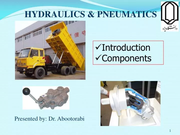
HYDRAULICS & PNEUMATICS • Introduction • Components Presented by: Dr. Abootorabi
Introduction Three basic methods of transmitting power: • Electrical • Mechanical • Fluid power In practice, most applications actually use combination of the three methods to achieve the most efficient overall systems.
Introduction • We have to understand the features of each method in order to get the best result. • For example, fluid systems can transmit power more economically over greater distance compare to mechanical systems. But fluid systems are restricted to shorter distances compared to electrical systems.
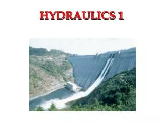
Definition • Hydraulics is the science of forces and movements transmitted by means of liquids.
Applications of hydraulic power Machine tools • Machine-tool construction is a typical area of application of hydraulics. With modern CNC machine tools, the tools and workpieces are clamped by hydraulic means. Feed motions and the spindle drive can also be hydraulically powered.
Press with elevated reservoir Applications of hydraulic power • This is an application in which extremely high forces are required. • A special feature is the elevated reservoir, which utilizes the static pressure in the pressure medium.
Mobile hydraulics: Excavator Applications of hydraulic power • On this hydraulic excavator, not only all working movements (linear drives) but also the propulsion of the vehicle (rotary drive) are hydraulically powered. The primary drive of the excavator is an internal-combustion engine.
Fluid power • Fluid power is divided into two: hydraulic system (using oils) and pneumatic system (using compressed air). • Each system has its own advantages and drawbacks. • There are many factors to consider to choose a suitable system.
Advantages of fluid power can be summarized as follows: • Ease and accuracy of control • Multiplication of force • Constant force or torque • Simplicity, safety, economy
Drawbacks of fluid power • Hydraulic oils are messy and leakage is impossible to eliminate completely. • Hydraulic lines can burst and might result in injuring people and damaging surrounding objects. • Prolonged exposure to loud noise can damage hearing. • Most hydraulic oils can cause fires if there is a leakage. • Compressive air for pneumatic systems can be dangerous if the pressure is too high.
Structure of a hydraulic system • This simplified block diagram shows the division of hydraulic systems into a signal control section and a hydraulic power section. This signal control section is used to activate the valves in the power control section.
Hydraulic power section • The diagram of the hydraulic power sectionis complemented in this case by a circuit diagram to allow correlation of the various function groups; the power supply section contains the hydraulic pump and drive motorand the components for the preparation of the hydraulic fluid. The power control section consists of the various valves used to provide control and regulate the flow rate, pressure and direction of the hydraulic fluid. The drive section consists of cylinders or hydraulic motors, depending on the application in question.
Components of a fluid power system: Hydraulic system A hydraulic system has six basic components: • A tank to hold the hydraulic oil • A pump to force the oil through the system • An electric motor or other power source to drive the pump • Valves to control oil direction, pressure and flow rate • An actuator to convert the pressure of the oil into mechanical force or torque to do useful work • Piping to carry the oil from one location to another
Components of a fluid power system: Hydraulic system • A tank (reservoir) to hold the hydraulic oil (A) • An electronic motor or other power source to drive the pump (B) • A pump to force the oil through the system (C) • Valves to control oil direction, pressure and flow rate (D-G) • An actuator to convert the pressure of the oil into mechanical force • or torque to do useful work (H) • Piping to carry the oil from one location to another
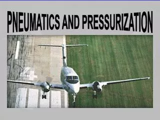
Components of a fluid power system: Pneumatic system A pneumatic system also has six basic components: • An air tank to store a certain volume of compressed air • A compressor to compress the air coming from the atmosphere • An electric motor or other prime mover to drive the compressor • Valves to control air direction, pressure, and flow rate. • Actuators, which are similar in operation to hydraulic actuators • Piping to carry the pressurized air from one location to another
Components of a fluid power system: Pneumatic system A pneumatic system also has six basic components:
Primary functions of a hydraulic fluid • Transmit power • Lubricate moving parts • Seal clearance between mating parts • Dissipate heat
Hydraulic fluid • In order to be safe, hydraulic fluids must also be changed periodically. • The frequency of changing depends on the fluid as well the operating conditions. • Advice from laboratory analysis could be sought to determine when the fluid should be changed.
Fluids: liquids and gases • A liquid is a fluid which has a definite volume independent of the shape of its container. • A liquid is considered to be incompressible so that its volume does not change with pressure changes. • This is only approximation but the change in volume due to pressure change is quite small that it is ignored for most engineering purposes.
Fluids: liquids and gases • A gas is a fluid which is compressible. • In addition, its volume will vary to fill the vessel containing it. • A gas is greatly influenced by the pressure to which it is subjected. • If the pressure increases, the volume decreases, and vice versa.
Fluids: liquids and gases • Air is the only gas commonly used in fluid power systems because it is inexpensive and readily available. • Air has the following desirable features: • Fire resistant • Not messy • Can be released back to atmosphere
Disadvantages of air • Due its compressibility, air cannot be used in an application requiring accurate positioning or rigid holding. • Because air is compressible, it tends to be sluggish. • Air can be corrosive since it contains oxygen (about 21%) and water. • A lubricant must be added to air to lubricate valves and actuators. • High pressure air (greater than 250 psi = 17 atm) is typically not used due to the explosive dangers.
Hydrostatic pressure • Hydrostatic pressure is the pressure created above a certain level within a liquid as a result of the weight of the liquid mass. Hydrostatic pressure is not dependent on the shape of the vessel concerned but only on the height and density of the column of liquid. • Hydrostatic pressure can generally be ignored for the purpose of studying hydraulics.
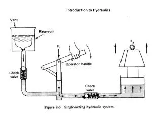
Pressure propagation • If a force F acts on an area A of an enclosed liquid, a pressure p is produced which acts throughout the liquid (Pascal's Law).
Power transmission • If a force F1 is applied to an area A1 of a liquid, a pressure p results. If, as in this case, the pressure acts on a larger surface A2, then a larger counter-force F2 must be maintained. If A2 is three times as large as A1, then F2 will also be three times as large as F1. • Hydraulic power transmission is comparable to the mechanical law of levers.
Displacement transmission • If the input piston of the hydraulic press travels a distances1, a volume of fluid will be displaced. This same volume displaces the output piston by the distance s2. If the area of this piston is larger than that of the input piston, the distance s2 will be shorter than s1.
Pressure transfer • The fluid pressure p1 exerts a force F1 on the surface A1 which is transferred via the piston rod to the small piston. The force F1 thus acts on the surface A2 and produces the fluid pressure p2 . Since the piston area A2 is smaller than the piston area A1, the pressure p2 must be larger than the pressure p1. • The pressure-transfer (pressure-intensification) effect is put to practical use in pneumatic/hydraulic pressure intensifiers and also in purely hydraulic systems when extremely high pressures are required which a pump cannot deliver.
Types of flow • A distinction is made between laminar flow and turbulent flow. In the case of laminar flow, the hydraulic fluid moves through the pipe in ordered cylindrical layers. If the flow velocity of the hydraulic fluid rises above a critical speed, the fluid particles at the center of the pipe break away to the side, and turbulence results. • Turbulent flow should be avoided in hydraulic circuits by ensuring they are adequate sized.
Types of flow • Laminar • Turbulent
Cavitation • Motion energy is required for an increase in the flow velocity of the oil at a restriction. This motion energy is derived from the pressure energy. If the vacuum which results is smaller than -0.3 bar, air dissolved in the oil is precipitated out. When the pressure rises again due to a reduction in speed, the oil bursts into the gas bubbles. • Cavitation is a significant factor in hydraulic systems as a cause of wear in devices and connections.
Cavitation • Local pressure peaks occur during cavitation. This causes the erosion of small particles from the wall of the pipe immediately after the reduced cross-section, leading to material fatigue and often also to fractures. This effect is accompanied by considerable noise.
Components of a hydraulic system • Power supply section:
Components of a hydraulic system • Power supply section:
Components of a hydraulic system • Power supply section:
Components of a hydraulic system • Hydraulic fluid: • Valves:
Components of a hydraulic system • Types of valves: • 1. Directional control valves:
Components of a hydraulic system • 2. Pressure valves: • 00
Components of a hydraulic system • 3. Flow control valves:
Components of a hydraulic system • 4. Non-return valves:
Components of a hydraulic system • Cylinders (linear actuators): • 1. Single-acting Cylinders:
Components of a hydraulic system • Cylinders (linear actuators): • 2. Double-acting cylinders:
Components of a hydraulic system • Motors (rotary actuators):
Components of a hydraulic system Tank (reservoir) for a hydraulic system: • The function of a tank is to store the fluid used. However, it serves functions other than storage and is actually a working part of the system. • A hydraulic reservoir or tank has the following functions: • Stores the hydraulic fluid of the system, including some reserve • Protects the stored fluid from outside contamination • Provides means to check the amount of fluid in the system • Provides means to addorchangethe fluid • Cools the fluid as it returns from the actuators, and • Removes contaminants such as water, dirt, pieces of metal, or chemicals from the fluid
Components of a hydraulic system Tank (reservoir) of a hydraulic system
Components of a hydraulic system Tank (reservoir) of a hydraulic system
Components of a hydraulic system • Most tanks are of welded construction with supports for mounting for easy access to the drain plug and also to permit cooling air to circulate underneath. • A tank must be totallyenclosedand should have a filteredairbreather to screen out particles from the surrounding air. • The fluid that flows in the hydraulic system must be cleaned. Contaminant are screened out using a strainer and a filter. Some reservoirs have magnetic plugs to trap iron and steel particles carried by the fluid.
Components of a hydraulic system • A strainer blocks the relatively large solid particles from entering the system. It is attached to the pumpinletline and may immersed in the oil near the bottom of the tank. Particles stuck to the strainer are cleanedofflater and the strainer is ready for reuse. • A filter is used to remove smaller particles by absorbing them. Fluid is allowed to flow through but fine particles are trapped and absorbed. When the filter becomes clogged, it is replaced by a new one.