Download
1 / 38
380 likes | 540 Views
Fundamentals of Ultrasonics. Ultrasonics. Definition : the science and exploitation of elastic waves in solids, liquids, and gases, which have a frequency above 20KHz. Frequency range : 20KHz-10MHz Applications : Non-destructive detection (NDE) Medical diagnosis

E N D
Ultrasonics Definition: the science and exploitation of elastic waves in solids, liquids, and gases, which have a frequency above 20KHz. Frequency range: 20KHz-10MHz Applications: • Non-destructive detection (NDE) • Medical diagnosis • Material characterization • Range finding • ……
Elastic wave Definition: An elastic wave carries changes in stress and velocity. Elastic wave is created by a balance between the forces of inertia and of elastic deformation. Particle motion: elastic wave induced material motion Wavespeed: the propagation speed of the elastic wave Particle velocity is much smaller than wavespeed
Wave Function Equation of progressive wave: • Amplitude: A • Wavelength: l • Frequency/Time period: f=1/T • Velocity U: U=fl=l/T • Energy: • Intensity:
Waveform & Wave front Waveform: the sequence in time of the motions in a wave
Propagation and Polarization Vector Propagation vector: the direction of wave propagation Polarization vector: the direction of particle motion
Wave Propagation • Body wave: wave propagating inside an object • Longitudinal (pressure) wave: deformation is parallel to propagation direction • Transverse (shear) wave: deformation is perpendicular to propagation direction, vT=0.5vL, generated in solid only • Surface wave: wave propagating near to and influenced by the surface of an object • Rayleigh wave: The amplitude of the waves decays rapidly with the depth of propagation of the wave in the medium. The particle motion is elliptical. vR=0.5vT • Plate Lamb wave: for thin plate with thickness less than three times the wavelength
Parameters of Ultrasonic Waves Velocity: the velocity of the ultrasonic wave of any kind can be determined from elastic moduli, density, and poisson’s ratio of the material • Longitudial wave: • is density and m is the Poisson’s Ratio • Transverse wave: • Surface wave:
Attenuation • Definition: the rate of decrease of energy when an ultrasonic wave is propagating in a medium. Material attenuation depends on heat treatments, grain size, viscous friction, crystal structure, porosity, elastic hysterisis, hardness, Young’s modulus, etc. • Attenuation coefficient: A=A0e-ax
Types of Attenuation • Scattering: scattering in an inhomogeneous medium is due to the change in acoustic impedance by the presence of grain boundaries inclusions or pores, grain size, etc. • Absorption: heating of materials, dislocation damping, magnetic hysterisis. • Dispersion: frequency dependence of propagation speed • Transmission loss: surface roughness & coupling medium.
Diffraction • Definition: spreading of energy into high and low energy bands due to the superposition of plane wave front. • Near Field: • Far Field: • Beam spreading angle:
Acoustic Impedance • Definition: the resistance offered to the propagation of the ultrasonic wave in a material, Z=rU. Depend on material properties only.
Reflection-Normal Incident • Reflection coefficient: • Transmission coefficient:
Reflection-Oblique Incident • Snell’s Law: • Reflection coefficient: • Transmission coefficient:
Mode Conversion When a longitudinal wave is incident at the boundary of A & B, two reflected beams are obtained. Selective excite different type of ultrasonic wave
Surface Skimmed Bulk Wave • The refracted wave travels along the surface of both media and at the sub-surface of media B
Resonance Quality factor
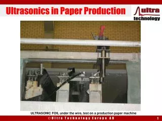
Typical Ultrasound Inspection System • Transducer: convert electric signal to ultrasound signal • Sensor: convert ultrasound signal to electric signal
Types of Transducers • Piezoelectric • Laser • Mechanical (Galton Whistle Method) • Electrostatic • Electrodynamic • Magnetostrictive • Electromagnetic
What is Piezoelectricity? • Piezoelectricity means “pressure electricity”, which is used to describe the coupling between a material’s mechanical and electrical behaviors. • Piezoelectric Effect • when a piezoelectric material is squeezed or stretched, electric charge is generated on its surface. • Inverse Piezoelectric Effect • Conversely, when subjected to a electric voltage input, a piezoelectric material mechanically deforms.
Quartz Crystals • Highly anisotropic • X-cut: vibration in the direction perpendicular to the cutting direction • Y-cut: vibration in the transverse direction
Piezoelectric Materials • Piezoelectric Ceramics (man-made materials) • Barium Titanate (BaTiO3) • Lead Titanate Zirconate (PbZrTiO3) = PZT, most widely used • The composition, shape, and dimensions of a piezoelectric ceramic element can be tailored to meet the requirements of a specific purpose. Photo courtesy of MSI, MA
Piezoelectric Materials • Piezoelectric Polymers • PVDF (Polyvinylidene flouride) film • Piezoelectric Composites • A combination of piezoelectric ceramics and polymers to attain properties which can be not be achieved in a single phase Image courtesy of MSI, MA
Piezoelectric Properties • Anisotropic • Notation: direction X, Y, or Z is represented by the subscript 1, 2, or 3, respectively, and shear about one of these axes is represented by the subscript 4, 5, or 6, respectively.
Piezoelectric Properties • The electromechanical coupling coefficient, k, is an indicator of the effectiveness with which a piezoelectric material converts electrical energy into mechanical energy, or vice versa. • kxy, The first subscript (x) to k denotes the direction along which the electrodes are applied; the second subscript (y) denotes the direction along which the mechanical energy is developed. This holds true for other piezoelectric constants discussed later. • Typical k values varies from 0.3 to 0.75 for piezoelectric ceramics. or
Piezoelectric Properties • The piezoelectric charge constant, d, relates the mechanical strain produced by an applied electric field, • Because the strain induced in a piezoelectric material by an applied electric field is the product of the value for the electric field and the value for d, d is an important indicator of a material's suitability for strain-dependent (actuator) applications. • The unit is Meters/Volt, or Coulombs/Newton
Piezoelectric Properties • The piezoelectric constants relating the electric field produced by a mechanical stress are termed the piezoelectric voltage constant, g, • Because the strength of the induced electric field in response to an applied stress is the product of the applied stress and g, g is important for assessing a material's suitability for sensor applications. • The unit of g is volt meters per Newton
SMART Layer for Structural Health Monitoring • Smart layer is a think dielectric film with built-in piezoelectric sensor networks for monitoring of the integrity of composite and metal structures developed by Prof. F.K. Chang and commercialized by the Acellent Technology, Inc. The embedded sensor network are comprised of distributed piezoelectric actuators and sensors. Image courtesy of FK Chang, Stanford Univ.
Piezoelectric Wafer-active Sensor • Read paper: • “Embedded Non-destructive Evaluation for Structural Health Monitoring, Damage Detection, and Failure Prevention” by V. Giurgiutiu, The Shock and Vibration Digest 2005; 37; 83 • Embedded piezoelectric wafer-active sensors (PWAS) is capable of performing in-situ nondestructive evaluation (NDE) of structural components such as crack detection. Image courtesy of V. Giurgiutiu, USC
Comparison of different PZ materials for Actuation and Sensing
Thickness Selection of a PZ transducer • Transducer is designed to vibrate around a fundamental frequency • Thickness of a transducer element is equal to one half of a wavelength
Different Types of PZ Transducer Normal beam transducer Dual element transducer Angle beam transducer Focus beam transducer
Characterization of Ultrasonic Beam • Beam profile or beam path • Near field: planar wave front • Far field: spherical wave front, intensity varies as the square of the distance • Determination of beam spread angle • Transducer beam profiling Near field planar wave front
Beam Profile vs. Distance Beam profile vs. distance Intensity vs. distance
Laser Generated Ultrasound (cont’) • Thermal elastic region: ultrasound is generated by rapid expansion of the material • Ablation region: ultrasound is generated by plasma formed by surface vaporization
Ultrasonic Parameter Selection • Frequency: • Penetration decreases with frequency • 1-10MHz: NDE work on metals • <1MHz: inspecting wood, concrete, and large grain metals • Sensitivity increases with frequency • Resolution increases with frequency and bandwidth but decrease with pulse length • Bream spread decrease with frequency • Transducer size: • active area controls the power and beam divergence • Large units provide more penetration • Increasing transducer size results in a loss of sensitivity • Bandwidth • A narrow bandwidth provides good penetration and sensitivity but poor resolution