Download

1 / 53
530 likes | 792 Views
Simulation in Digital communication. chapter # 7 Digital Transmission Via Carrier Modulation. Carrier-Amplitude modulation. In baseband digital PAM:. (2d - the Euclidean distance between two adjacent points). the transmitted signal waveforms:. special case:. rectangular pulse.

E N D
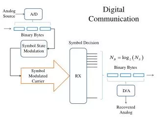
Simulation in Digital communication
chapter # 7 Digital Transmission Via Carrier Modulation
Carrier-Amplitude modulation In baseband digital PAM: (2d - the Euclidean distance between two adjacent points)
the transmitted signal waveforms: special case: rectangular pulse
the Amplitude modulated Carrier signal is usually called amplitude shift keying (ASK)
r W- W 0 Figure 7.1: Energy density spectrum of the transmitted signal gT(t).
Figure 7.2: amplitude modulation of a sinusoidal carrier by the baseband PAM signal
f - fc - W - fc - fc + W 0 fc - W fc fc + W (b) 1 r W- W 0 (a) Figure 7.3: Spectra of (a) baseband and (b) amplitude-modulated signal.
-5d -3d -d 0 d 3d 5d Figure 7.4: Signal points that take M values on the real line The baseband PAM signal waveforms in general:
when we cross correlate the signal r(t) with the signal waveform we get: the variance can expressed as:
X X Figure 7.5: Demodulation of bandpass digital PAM signal.
Example 7.1: In an amplitude-modulated digital PAM system, the transmitter filter with impulse response gT(t) has a square-root raised-cosine spectral characteristic as described in Illustrative problem 6.7, with a roll-off factor a=0.5. The carrier frequency is fc=40/T. evaluate and graph the spectrum of baseband signal and the spectrum of the amplitude-modulatedsignal Answer ip_07_01
Carrier-Phase Modulation This type of digital phase modulation is called Phase-Shift-Key where gT(t) is the transmitting filter pulse shape.
when gT(t) is a rectangular pulse we expressed the transmitted signal waveform (at 0 < t <T) as:
Example 7.2: Generate the constant-envelope PSK signal waveforms given by (1.3.4) for M=8. For convenience, the signal amplitude is normalized to unity. Answer ip_07_02
00 01 E E s s E E 11 10 M= 4 M= 2 011 001 010 000 110 100 111 101 Figure 7.8:PSK signal constellations M=8
Phase Demodulation and Detection the two quadrature components of the additive noise
the received signal vector r is projected onto each of the M possible transmitted signal vector {Sm}and select the vector corresponding to the largest projection. The correlation metrics we select the {Sm} signal whosh phase is the closet
Example 7.3: We shall perform a Monte Carlo simulation of M=4 PSK communication system that models the detector as the one that computes the correlation metrics given in (7.3.15). The model for the system to be simulated is shown in Figure 7.11. Answer ip_07_03 Uniform random number generator Gaussian RNG 4-PSK MAPPER 2-bit symbol + Detector + Gaussian RNG compare Bit-error counter Symbol-error counter Figure 7.11:Block diagram of an M=4 PSK system for Monte Carlo simulation
X X Block diagram of DPSK demodulator
Example 7.4: implement a differential encoder for the case of m=8 DPSK. Answer ip_07_04
Example 7.5: Perform a Monte Carlo simulation of an M=4 DPSK communication Answer ip_07_05
Uniform random number generator Gaussian RNG 4-DPSK MAPPER + Delay M=4DPSK Detector 2-bit output + Gaussian RNG compare Symbol-error counter Figure 7.15: Block diagram of m=4 DPSK system for the Monte Carlo simulation
Quadrature Amplitude Modulation the transmitted signal waveform the combined digital amplitude and digital-phase modulation form
Transmitting filter gT(t) Balanced modulator Oscillator Serial-to- parallel converter Binary data + 90 Phase shift Transmitted QAM signal Transmitting filter gT(t) Balanced modulator Functional block diagram of modulator for QAM
Quadrature Amplitude demodulation X X X X Demodulation and detection of QAM signals
Example 7.6: perform a Monte Carlo simulation of am M=16-QAM communication system using a rectangular signal constellation. The model of the system to be simulated is shown in figure 7.22. Answer ip_07_06 Uniform random number generator Gaussian RNG M=16-QAM signal selector 4-bit symbol + Detector + Gaussian RNG compare Bit-error counter Symbol-error counter Figure:Block diagram of an M=16-QAM system for the Monte Carlo simulation
Demodulation and detection of FSK signals the filter received signal at the input phase shift The additive bandpass noise
Sample at t=T PLL1 Sample at t=T Received signal PLL1 Output decision Sample at t=T PLL1 Figure 7.26: Phase-coherent demodulation of M-ary FSK signals.
r1c Sample at t=T r1c r1c Detector Output decision Received signal r1c Sample at t=T r1c Sample at t=T r1c Sample at t=T Figure 7.26: Demodulation of M-ary signals for noncoherent detection .
Example 7.7:Consider a binary communication system that employs the two FSK signal waveforms given as Answer ip_07_07 Where f1 =1000/Tb and f2= f1+1/Tb. The channel imparts a phase shift of =45 on each of the transmitted signals, so that the received signal in the absence of noise is Numerically implement the correlation-type demodulator for FSK signals.
Example 7.8: perform a Monte Carlo simulation of a binary FSK communication system in which the signal waveforms are givenby(7.5.1) wheref2 = f2 +1/ Tband the detector is a square-law detector. The block diagram of the the binary FSK system to be simulated is shown in Figure 7.30. Answer ip_07_08 Uniform RNG Uniform RNG Uniform RNG 2 ( ) FSK signal selector Output bit 2 ( ) Detector 2 ( ) 2 ( ) Gaussian RNG Gaussian RNG compare Bit-error counter Figure7.30: Block diagram of a binary FSK system for the Monte Carlo simulation
Synchronization in Communication Systems Carrier Synchronization: A local oscillator whose phase is controlled to be synch with the carrier signal. Phase-Locked Loop: A nonlinear feedback control sys for controlling the phase of the local oscillator . the input to the PLL
the input of the loop filter ( e(t) has a high and a low frequency component. ) The role of the loop filter is to remove the high frequency component.
Input signal r(t) + - Figure 7.33: The phase-locked loop after removal of high-frequency components
+ - Figure 7.34: The linearized model for a phase-locked loop.
Example 7.9:[First-order PLL] Assuming that Answer ip_07_09 And K=1, determine and plot the response of thePLL to an abrupt change of height 1 to the input phase.
Clock Synchronization early-late gate: A simple implementation of clock synch based on the fact that in a PAM communication sys the output of the matched filter is the autocorrlation function of the basic pulse signal used in the PAM sys. The autocorrlation function is MAX and symmetric