Download
1 / 34
340 likes | 489 Views
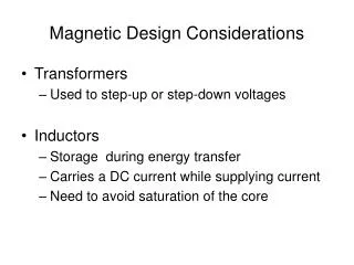
Multicore Design Considerations. Multicore: The Forefront of Computing Technology .

E N D
Multicore: The Forefront of Computing Technology • “We’re not going to have faster processors. Instead, making software run faster in the future will mean using parallel programming techniques. This will be a huge shift.” -- Katherine Yelick, Lawrence Berkeley National Laboratoryfrom The Economist: Parallel Bars • Multicore is a term associated with parallel processing, which refers to the use of simultaneous processors to execute an application or multiple computational threads. • Parallel programming/processing can be implemented on TI’s KeyStone multicore architecture.
Parallel Processing • Parallel processing divides big applications into smaller applications and distributes tasks across multiple cores. • The goal is to speed up processing of a computationally-intensive applications. • Characteristics of computationally-intensive applications: • Large amount of data to process • Complex algorithms require many computations • Goals of task partitioning • Computational load balancing evenly divides effort among all available cores • Minimizes contention of system resources • Memory (DDR, shared L2) • Transport (Teranet, peripherals)
Parallel Processing: Use Cases • Network gateway, speech/voice processing • Typically hundreds or thousands of channels • Each channel consumes about 30 MIPS • Large, complex, floating point FFT (1M) • Multiple-size, short FFTs • Video processing • Slice-based encoder • Video transcoder (low quality) • High-quality decoder
Parallel Processing: Use Cases • Medical imaging • Filtering > reconstruction > post filtering • Edge detection • LTE channel excluding turbo decoder/encoder • Two cores uplink • Two cores downlink • LTE channel including turbo decoder • Equal to the performance of 30 cores • Each core works on a package of bits • Scientific processing • Large complex matrix manipulations • Use Case: Oil exploration
Parallel Processing: Control Models Master Slave Slave Slave Core 1 Core 0 Core 2 • Master Slave Model • Multiple speech processing • Variable-size, short FFT • Video encoder slice processing • VLFFT • Data Flow Model • High quality video encoder • Video decoder • Video transcoder • LTE physical layer
Parallel Processing: Partitioning Considerations • Function driven • Large tasks are divided into function blocks • Function blocks are assigned to each core • The output of one core is the input of the next core • Use cases: H.264 high quality encoding and decoding, LTE • Data driven • Large data sets are divided into smaller data sets • All cores perform the same process on different blocks of data • Use cases: image processing, multi-channel speech processing, sliced-based encoder
Parallel Processing: System Recommendations • Ability to perform many operations • Fixed-point AND floating-point processing • SIMD instruction, multicore architecture • Ability to communicate with the external world • Fast two-way peripherals that support high bit-rate traffic • Fast response to external events • Ability to address large external memory • Fast and efficient save and retrieve methods • Transparent resource sharing between cores • Efficient communication between cores • Synchronization • Messaging • Data sharing
Parallel Processing: Recommended Tools • Easy-to-use IDE (Integrated Development Environment) • Advanced debug features (system trace, CP tracer) • Simultaneous, core-specific debug monitoring • Real-time operating system (e.g., SYS/BIOS) • Multicore software development kit • Standard APIs simplifies programming • Layered abstraction hides physical details from the application • System optimized capabilities • Full-featured compiler, optimizer, linker • Third-party support
Example: High Def 1080i60 Video H264 Encoder • A short introduction to video encoding • Pixel format • Macroblocks • Performance numbers and limitations • Motion estimation • Encoding • Entropy encoder • Reconstruction • Data in and out of the system • DDR bandwidth • Synchronization, data movement • System architecture
Macroblock and Pixel Data RGB and YUV 4:4:4 and 4:2:0 format • Typically 8-bit values (10, 12, 14) • Macroblock = 16x16 pixels 4:2:0 4:4:4 -- Pixel with only Y value -- Pixel with only Cr and Cb values -- Pixel with Y, Cr, and Cb values macroblock
Video Coding Algorithm Limitations • Motion estimation • Depends on the reconstruction of previous (and future) frames • Shortcuts can be performed (e.g., first row of frame N does not need last row of frame N-1). • Intra-prediction • Depends on the macroblock above and to the left • Must be done consecutively or encoding efficiency is lost (i.e., lower quality for the same number of bits) • Entropy encoding (CABAC, CAVLC) • Must be processed in the macroblock order • Each frame is independent of other frames.
How Many Channels Can One C6678 Process? • Looks like two channels;Each one uses four cores. • Two cores for motion estimation • One core for entropy encoding • One core for everything else • What other resources are needed? • Streaming data in and out of the system • Store and load data to and from DDR • Internal bus bandwidth • DMA availability • Synchronization between cores, especially if trying to minimize delay
What are the System Input Requirements? • Stream data in and out of the system: • Raw data: 1920 * 1080 * 1.5 = 3,110,400 bytes per frame= 24.883200 bits per frame (~25M bits per frame) • At 30 frames per second, the input is 750 Mbps • NOTE: The order of raw data for a frame is Y component first, followed by U and V • 750 Mbps input requires one of the following: • One SRIO lane (5 Gbps raw, about 3.5 Gbps of payload), • One PCIe lane (5 Gbps raw) • NOTE: KeyStone devices provide four SRIO lanes and two PCIe lanes • Compressed data (e.g., 10 to 20 Mbps) can use SGMII (10M/100M/1G) or SRIO or PCIe.
How Many Accesses to the DDR? • For purposes of this example, only consider frame-size accesses. • All other accesses (ME vectors, parameters, compressed data, etc.) are negligible. • Requirements for processing a single frame: • Retrieving data from peripheral to DDR - 25M bits = 3.125MB • Motion estimation phase reads the current frame (only Y) and older Y component of reconstruction frame(s). • A good ME algorithm may read up to 6x older frame(s). • 7 * 1920 * 1088 = ~ 15M Bytes • Encoding phase reads the current frame and one old frame. The total size is about 6.25 MB. • Reconstruction phase reads one frame and writes one frame. So the total bandwidth is 6.25 MB. • Frame compression before or after the entropy encoder is negligible. • Total DDR access for a single frame is less than 32 MB.
How Does This Access Avoid Contention? • Total DDR access for a single frame is less than 32 MB. • The total DDR access for 30 frames per second (60 fields) is less than 32 * 30 = 960 MBps. • The DDR3 raw bandwidth is more than 10 GBps (1333 MHz clock and 64 bits). 10% utilization reduces contention possibilities. • DDR3 DMA uses TeraNet with clock/3 and 128 bits. TeraNet bandwidth is 400 MHz * 16B = 6.4 GBps.
KeyStone SoC Architecture Resources • 10 EDMA transfer controllers with 144 EDMA channels and 1152 PaRAM (parameter blocks) • The EDMA scheme must be designed by the user. • The LLD provides easy EDMA usage. • In addition, Navigator has its own PKTDMA for each master. • Data in and out of the system (SRIO, PCIe or SGMII) is done using the Navigator. • All synchronization between cores and moving pointers to data between cores is done using the Navigator. • IPC provides easy access to the Navigator.
Conclusion • Two H264 high-quality 1080i encoders can be processed on a single TMS320C6678
Very Large Fast DFT (VL FFT)ImplemHigh-Performance Parallel FFT Algorithmsfor the HITACHI SR8000Daisuke TakahashiInformation Technology Center, University of Tokyo2-11-16 Yayoi, Bunkyo-ku, Tokyo 113-8658, Japandaisuke@pi.cc .u-tokyo.ac. j pentationon KeyStone VLFFT
Outlines Basic Algorithm for Parallelizing DFT Multi-core Implementation of DFT Review Benchmark Performance
Goals and Requirements • Goal: • To implement very large floating point fast DFT on TI multicore devices: Shannon and Nyquist • Requirements: • FFT sizes: 4K – 1M samples • Configurable to run on different number of cores: 1, 2, 4, 8 • High performance
Algorithm for Very Large DFT • Here N is the total size of DFT , A generic discrete Fourier transform (DFT) is shown below,
Algorithm for Very Large DFT • A vary large DFT of size N=N1*N2 can be computed in the following steps: • Formulate input into N1xN2 matrix • Matrix transpose: N1xN2 -> N2xN1 • Compute N2 FFTs size N1 • Multiply Global twiddle factors • Matrix transpose: N2xN1 -> N1xN2 • Compute N1 FFTs. Each is N2 size. • Matrix transpose: N1xN2 -> N2xN1
Implementing VLFFT on Multiple Cores • Two iterations of computations • 1st iteration • N2 FFTs are distributed across all the cores. • Each core implements matrix transpose and computes N2/numCores FFTs and multiplying twiddle factor. • 2nd iteration • N1 FFTs of N2 size are distributed across all the cores • Each core computes N1/numCores FFTs and implements matrix transpose before and after FFT computation.
Data Buffers • DDR3: Three float complex arrays of size N • Input buffer, output buffer, working buffer • L2 SRAM: • Two ping-pong buffers, each buffer is the size of 16 FFT input/output • Some working buffer • Buffers for twiddle factors • Twiddle factors for N1 and N2 FFT • N2 global twiddle factors
Global Twiddle Factors • Global Twiddle Factors: • Total of N1*N2 global twiddle factors are required. • N1 are actually pre-computed and saved. • The rest are computed during run time.
DMA Scheme • Each core has dedicated in/out DMA channels • Each core configures and triggers its own DMA channels for input/output • On each core, the processing is divided into blocks of 8 FFT each. • For each block on every core • DMA transfer 8 lines of FFT input • DSP computes FFT/transpose • DMA transfers 8 lines of FFT output
VLFFT Pseudo Code VLFFT_start: 1) Core0 sends message to each core to start 1st iteration processing. 2) Each core does the following, Wait message from core 0 to start, numBlk = 0; While( numBlk < totalBlk ) { 1) Trigger DMA to transfer (n+1)th blk from Input Buffer to L2 and to transfer (n-1)th blk output from L2 to Temp Buffer 2) Implement transpose, compute FFT, and multiply twiddle factors for nth blk 3) wait for DMA completion 4) numBlk++ } Send a message to core 0 3) Core0 waits for message from each core for completion of its own processing 4) After receiving all the messages from all the other cores, core0 sends message to each core to start 2nd iteration processing 5) Each core does the following, Wait message from core 0 to start, numBlk = 0; While( numBlk < totalBlk ) { 1) Trigger DMA to transfer (n+1)th blk from Temp Buffer to L2 and to transfer (n-1)th blk output from L2 to Output Buffer 2) Compute FFT and transpose for nth blk 3) wait for DMA completion 4) numBlk++ } Send a message to core 0 6) Core0 waits for message back from each core for completion its own processing VLFFT_end:
Matrix Transpose • The transpose is required for the following matrixes from each core: • N1x8 -> 8xN1 • N2x8 -> 8xN2 • 8xN2 -> N2x8 • DSP computes matrix transpose from L2 SRAM • DMA bring samples from DDR to L2 SRAM • DSP implements transpose for matrixes in L2 SRAM • 32K L1 Cache
Major Kernels FFT: single precision floating point FFT from c66x DSPLIB Global twiddle factor compute and multiplication: 1 cycle per complex sample Transpose: 1 cycle per complex sample
Major Software Tools SYS BIOS 6 CSL for EDMA configuration IPC for inter-processor communication
Conclusion After the demo …