Download
1 / 38
380 likes | 411 Views
Extrusion and Drawing of Metals. Introduction. Extrusion – It is a process where a billet is forced through a die. Parts have constant cross-section

E N D
Extrusion and Drawing of Metals
Introduction Extrusion – It is a process where a billet is forced through a die. • Parts have constant cross-section • Typical Products of Extrusion – Sliding Doors, tubing having various cross-sections, structural and architectural shapes and door and window frames. Drawing – It is a process where a cross-section of solid rod, wire, or tubing is reduced or changed in shape by pulling it through a die.
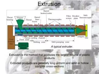
Extrusion Compression forming process in which the work metal is forced to flow through a die opening to produce a desired cross‑sectional shape • Process is similar to squeezing toothpaste out of a toothpaste tube • In general, extrusion is used to produce long parts of uniform cross-sections
Extrusions Fig : Extrusions and examples of products made by sectioning off extrusions.
Types of Extrusion Process Direct Extrusion (or) Forward Extrusion – Billet is placed in a chamber and forced through a die opening by a hydraulically-driven ram or pressing stem. Indirect Extrusion(or) Backward Extrusion – Die moves towards the billet. Hydrostatic Extrusion – The billet is smaller in diameter that the chamber, which is filled with a fluid, and the pressure is transmitted to the billet by a ram. Lateral Extrusion – Impact extrusion -
Direct Extrusion Fig : Schematic illustration of direct extrusion process.
Comments on Direct Extrusion • Also called forward extrusion • As ram approaches die opening, a small portion of billet remains that cannot be forced through die opening • This extra portion, called the butt, must be separated from extruded product by cutting it just beyond the die exit • Starting billet cross section usually round, but final shape is determined by die opening
Figure 19.32 ‑ (a) Direct extrusion to produce a hollow or semi‑hollow cross‑section; (b) hollow and (c) semi‑hollow cross‑ sections
Indirect Extrusion Fig : Schematic illustration of direct extrusion process.
Figure 19.33 ‑ Indirect extrusion to produce (a) a solid cross‑section and (b) a hollow cross‑section
Comments on Indirect Extrusion • Also called backward extrusion and reverse extrusion • Limitations of indirect extrusion are imposed by the lower rigidity of hollow ram and difficulty in supporting extruded product as it exits die
General Advantages of Extrusion • Variety of shapes possible, especially in hot extrusion • Limitation: part cross‑section must be uniform throughout length • Grain structure and strength enhanced in cold and warm extrusion • Close tolerances possible, especially in cold extrusion • In some operations, little or no waste of material
Hot vs. Cold Extrusion • Hot extrusion - prior heating of billet to above its recrystallization temperature • This reduces strength and increases ductility of the metal, permitting more size reductions and more complex shapes • Cold extrusion - generally used to produce discrete parts • The term impact extrusion is used to indicate high speed cold extrusion
Extrusion Ratio Also called the reduction ratio, it is defined as: where rx = extrusion ratio; Ao= cross-sectional area of the starting billet; and Af= final cross-sectional area of the extruded section • Applies to both direct and indirect extrusion
Figure 19.36 ‑ (a) Definition of die angle in direct extrusion; (b) effect of die angle on ram force
Comments on Die Angle • Low die angle - surface area is large, leading to increased friction at die‑billet interface • Higher friction results in larger ram force • Large die angle - more turbulence in metal flow during reduction • Turbulence increases ram force required • Optimum angle depends on work material, billet temperature, and lubrication
Comments on Orifice Shape of Extrusion Die • Simplest cross section shape = circular die orifice • Shape of die orifice affects ram pressure • As cross‑section becomes more complex, higher pressure and greater force are required
Figure 19.37 ‑ A complex extruded cross‑section for a heat sink (photo courtesy of Aluminum Company of America)
Extrusion Presses • Either horizontal or vertical • Horizontal more common • Extrusion presses - usually hydraulically driven, which is especially suited to semi‑continuous direct extrusion of long sections • Mechanical drives - often used for cold extrusion of individual parts
Hydrostatic Extrusion • The pressure required for extrusion is supplied through and incompressible fluid medium surrounding the billet • Usually carried at room temperature, typically using vegetable oils as the fluid • Brittle materials are extruded generally by this method • It increases ductility of the material • It has complex nature of the tooling
Similar to indirect extrusionPunch descends rapidly on the blank, which is extruded backward Impact Extrusion
Examples of Impact Extrusion Fig : (a) Two examples of products made by impact extrusion. These parts may also be made by casting, by forging, or by machining; the choice of process depends on the dimensions and the materials involved and on the properties desires. Economic considerations are also important in final process selection. (b) and (c) Impact extrusion of a collapsible tube by the Hooker process.
Surface cracking. Pipe. Internal Cracking Fig : (a) Chevron cracking (central burst) in extruded round steel bars. Unless the products are inspected, such internal defects may remain undetected, and later cause failure of the part in service. This defect can also develop in the drawing of rod, of wire, and of tubes. (b) Schematic illustration of rigid and plastic zones in extrusion. The tendency toward chevron cracking increases if the two plastic zones do not meet. Note that the plastic zone can be made larger either by decreasing the die angel or by increasing the reduction in cross-section (or both). Extrusion Defects
Wire and Bar Drawing Cross‑section of a bar, rod, or wire is reduced by pulling it through a die opening • Similar to extrusion except work is pulled through die in drawing (it is pushed through in extrusion) • Although drawing applies tensile stress, compression also plays a significant role since metal is squeezed as it passes through die opening
Area Reduction in Drawing Change in size of work is usually given by area reduction: where r = area reduction in drawing; Ao = original area of work; and Af = final work
Wire Drawing vs. Bar Drawing • Difference between bar drawing and wire drawing is stock size • Bar drawing - large diameter bar and rod stock • Wiredrawing - small diameter stock - wire sizes down to 0.03 mm (0.001 in.) are possible • Although the mechanics are the same, the methods, equipment, and even terminology are different
Drawing Practice and Products • Drawing practice: • Usually performed as cold working • Most frequently used for round cross‑sections • Products: • Wire: electrical wire; wire stock for fences, coat hangers, and shopping carts • Rod stock for nails, screws, rivets, and springs • Bar stock: metal bars for machining, forging, and other processes
Bar Drawing • Accomplished as a single‑draft operation ‑ the stock is pulled through one die opening • Beginning stock has large diameter and is a straight cylinder • This necessitates a batch type operation
Wire Drawing • Continuous drawing machines consisting of multiple draw dies (typically 4 to 12) separated by accumulating drums • Each drum (capstan) provides proper force to draw wire stock through upstream die • Each die provides a small reduction, so desired total reduction is achieved by the series • Annealing sometimes required between dies
Features of a Draw Die • Entry region - funnels lubricant into the die to prevent scoring of work and die • Approach - cone‑shaped region where drawing occurs • Bearing surface - determines final stock size • Back relief - exit zone - provided with a back relief angle (half‑angle) of about 30 • Die materials: tool steels or cemented carbides
Preparation of the Work for Wire or Bar Drawing • Annealing – to increase ductility of stock • Cleaning - to prevent damage to work surface and draw die • Pointing – to reduce diameter of starting end to allow insertion through draw die
Tube Drawing Operations Fig : Examples of tube-drawing operations, with and without internal mandrel. Note that a variety of diameters and wall thickness can be produced from the same initial tube stock (which had been made by other processes).