Download
1 / 13
130 likes | 134 Views
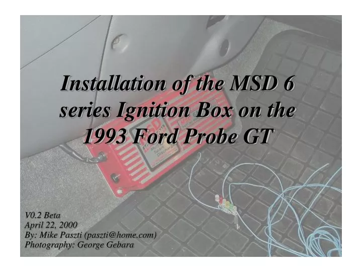
Installation of the MSD 6 series Ignition Box on the 1993 Ford Probe GT. V0.2 Beta April 22, 2000 By: Mike Paszti (paszti@home.com) Photography: George Gebara. Contents External coil tower (the screw) Transistor hook-up, and MSD box hook-up Schematic Miscellaneous notes

E N D
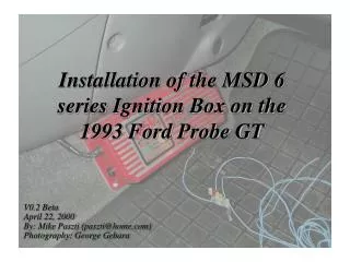
Installation of the MSD 6 series Ignition Box on the 1993 Ford Probe GT V0.2 Beta April 22, 2000 By: Mike Paszti (paszti@home.com) Photography: George Gebara
Contents • External coil tower (the screw) • Transistor hook-up, and MSD box hook-up • Schematic • Miscellaneous notes • What You Will Need • MSD 6A series ignition box • MSD or other suitable external ignition coil • 3055 NPN transistor • 1k resistor (1/4W or greater)
External Coil Tower The external coil tower is a screw that is screwed into the distributor cap so as to allow the high voltage output of an external coil to enter the distributor in order to be distributed to the cylinders. The screw is driven through the cap so that it contacts the metal strip embedded in the plastic. This strip is common with (i.e., electrically connected to) the rotor inside the cap. Epoxy is used to reinforce the screw and provide a secure fit for the plug wire boot.
External Coil Tower Epoxy reinforcement Metal strip runs internally along dashed line Screw with shaved down head My own repair (unrelated)
Transistor Hook-up The transistor used in this project is a TIP3055 NPN transistor. It is readily available at Radio Shack for a few dollars. The 3055 transistor is what triggers the MSD box to fire a spark. The transistor is triggered by the ECU. By using the 3055, the internal ignitor module is completely bypassed.
Transistor Hook-up C Ignore this diode. It is not required. cut B MSD white wire cut e B, C A cut f f cut e cut a c b d
Transistor Hook-up The following wires are cut at the distributor: - A - B - C - e - f Connections to these wires are all made on the engine side of the cut wire (not the distributor side).
Transistor Hook-up Connect to ‘e’: Connection to ground. The ground wire ‘e’ can be identified by its all black colour. - MSD Box white wire - ‘A’:ECU requires this signal to operate Connect to Connect to ‘B’(note 1k resistor): This is the tachometer signal Connect to‘f’:This is the trigger signal from the ECU. This wire will have a coloured stripe on it.
MSD Box Hook-up Thick Black Wire: Ground to frame Thin Black Wire: To external coil ‘-’ MSD 6A Thick Red Wire: To battery + or high current fused line Thin Red Wire: Ignition switch (‘C’) White Wire: Connect to middle lead on transistor Orange Wire: To external coil “+”
Schematic Thick Black Wire: Ground to frame MSD 6A Thick Red Wire: To battery + or high current fused line ‘C’ ‘f’ 3055 ‘e’ Distributor Cap + - ‘B’ 1k resistor External Coil ‘A’
Miscellaneous Notes • Mazda/Ford made subtle changes to the distributor between model years. In some model years wires ‘A’ and ‘B’ are switched. • As noted earlier, ‘e’ and ‘f’ are incorrectly identified in the Ford Service Manual. If in doubt, the ground wire ‘e’ can be identified by its all black colour. • There appears to be some differences between the 1993 Probe GT tachometer electronics and those of the Mazda 626/MX-6. This writer was unsuccessful in making the tachometer work on a 1994 Mazda 626 with a MSD 6A BTM even though the exact same set-up worked on a 1993 Probe GT. The MSD tachometer adapter may resolve this problem. • As noted earlier, regarding the wires that are cut at the distributor, all connections are made to the “engine” side of the wires. • The cut connections on the distributor side, particularly ‘A’, ‘B’, and ‘C’, should be electrically insulated to prevent shorting.