Download
1 / 63
630 likes | 1.04k Views
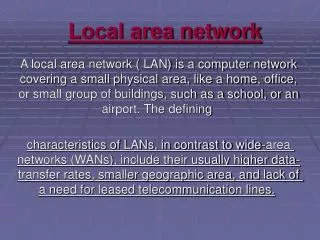
LOCAL AREA NETWORS. A local area network (LAN) is a data communication system that allows a number of independent devices to communicate directly with each other in a limited geographic area. There are four basic architectures: Ethernet Token Bus Token Ring Fiber Distributed Interface (FDDI)

E N D
A local area network (LAN) is a data communication system that allows a number of independent devices to communicate directly with each other in a limited geographic area. • There are four basic architectures: • Ethernet • Token Bus • Token Ring • Fiber Distributed Interface (FDDI) Ethernet, token bus, token ring are standards of the IEEE and are part of its project 802; FDDI is an ANSI standard.
The logical link control (LLC) is the upper part sublayer of the data link layer (logical addresses, control information, an data) • Media Access Control (MAC) sublayer resolves the contention for the shared media.
Access Method: CSMA/CD • The Ethernet architecture does not have a regulated access to the medium. • Whenever multiple users have unregulated access to a single line, there is a danger of signals overlapping and destroying each other. Such overlaps, which turn the signals into unusable noise, are called collisions. • As traffic increases on a multiple-access link, so do collisions.
Access Method: CSMA/CD • The access mechanism used in an Ethernet is called carrier sense multiple access with collision detection CSMA/CD • In CSMA/CD system, any workstation wishing to transmit must first listen for existing traffic on the line. A device listens by checking for a voltage. If no voltage is detected, the line is considered idle and the transmission is initiated. During the data transmission, the station checks the line for the extremely high voltages that indicate a collision.
If a collision is detected, the station quits the current transmission and waits a predetermined amount of time for the line to clear, then sends its data again. http://www.mhhe.com/engcs/compsci/forouzan/dcn/student/olc/animations/12_06.swf Addressing Each station on an Ethernet network has its own network interface card (NIC). The NIC usually fits inside the station and provides the station with a six-byte physical address. The number on the NIC is unique. Data Rate Ethernet LANs can support data rates between 1 and 100Mbps.
Frame Format • IEEE 802.3 specifies one type of frame containing seven fields:
Preamble The preamble contains seven bytes (56 bits) of alternating 0s and 1s that alert the receiving system to the coming frame and enable it to synchronize its input timing. • Start Frame delimiter SFD The SFD tells the receiver that everything that follows is data, starting with the addresses. • Destination Addresses DA The DA field contains the physical destination address (six bytes) of the packet’s next destination. If the packet must across from one LAN to another to reach its destination, the DA field contains the physical address of the router connecting the current LAN to the next one.
Source Address The SA field contains the physical address ( six bytes) of the last device to forward the packet. That device can be the sending station or the most recent router to receive and forward the packet. • Length/type of Protocol Data Unit (PDU) This field contains two bytes indicating the number of bytes in the PDU. If the length of the PDU is fixed, this field can be used to indicate type, or as a base for other protocols. Protocol Data Unit PDU The PDU is generated by the upper LLC sublayer, then linked to the 802.3 frame. The PDU can be anywhere from 46 to 1500 bytes long, depending on the type of frame and the length of the information field.
CRC The last field in the 802.3 frame contains the error detection information, in this case CRC-32.
Implementation • Ethernet LANs are configured as logical buses, although they may be physically implemented in bus or star topologies. • Each frame is transmitted to every station on the link but read only by the station to which it is addressed.
10BASE5: Thick Ethernet • 10Base5 is a bus topology LAN that uses based signaling and has a maximum segment length of 500 meters. • To reduce collisions, the total length of the bus should not exceed 2500 meters (five segments). • Also, the standard demands that each station be separated from each neighbor by 2.5 meters.
10BASE5: Thick Ethernet • The physical components includes coaxial cable, network interface cards, transceivers, and attachment unit interface (AUI) cables. • RG-8 cable is thick coaxial cable that provides the backbone of the IEEE802.3 standard. • Transceiver Each station is attached by an AUI cable to an intermediary device called a medium attachment unit (MAU) or transceiver.
10BASE5: Thick Ethernet • The transceiver performs CSMA/CD function of checking for voltages and collisions on the line and may contain an small buffer. It also serves as the connector that attaches a station to the thick coaxial cable itself via a tap. • AUI cables Each station is linked to its corresponding transceiver by an attachment unit interface (AUI), also called a transceiver cable. AUIs are restricted to a maximum length of 50 meters.
10BASE5: Thick Ethernet • Transceiver tap Each transceiver contains a connecting mechanism, called a tap because it allows the transceiver to tap into the line at any point.
10BASE2:Thin Ethernet • Like 10Base5, 10Base2 is a bus topology LAN. The advantages of thin Ethernet are reduced cost and ease of installation. • The disadvantages are shorter range (185 meters) • The NICs in a thin Ethernet system provide all the same functionality as those in a thick Ethernet, plus the functions of the transceivers. • The cable required to implement the 10Base2 standard is RG-58. These cables are relatively easy to install and move.
10Base-T: Twisted-Pair Ethernet • A star-topology LAN using unshielded twisted pair (UTP) cable instead of coaxial cable. • It supports a data rate of 10Mbps and has a maximum length (hub to station) of 100 meters. • It requires a hub with a port for each station. The hub fans out any transmitted frame to all to all its connected stations.
1Base5: Star LAN • Star-LAN is an AT&T product used infrequently today because of its slow speed. • Star-LAN allows as many as 10 stations to be linked, each to the next, in a chain in which only the lead device connects to the hub.
10Base-FL: Fiber Link Ethernet 10Base-FL uses a star topology to connect stations to a hub. The standard is normally implemented using an external transceiver called fiber-optic MAU. The station is connected to the external transceiver by an AUI cable. The transceiver is connected to the hub by using two pairs of fiber-optic cables.
Switched Ethernet • The 10Base-T Ethernet is a shared media network, which means that the entire media is involved in each transmission. Any frame produced by one station is retransmitted by the hub to all stations in the network. Thus, if two stations try to send frames simultaneously, there is a collision.
Switched Ethernet • If we replace the hub by a switch, a device that can recognize the destination address and can route the frame to the port to which the destination station is connected, the rest of the media are not involved in the transmission process.
Full-duplex switched Ethernet • One of the limitations of 10Base5 and 10Base2 is that the communication is half-duplex. • In Full-duplex switched Ethernet each station is connected to the switch through two links: one to transmit and one to receive. • The speed passes from 10Mbps to 20Mbps. • There is no need for the CSMA/CD method.
Fast Ethernet • Fast Ethernet operates to 100 Mbps. • Star topology 100Base-TX • The 100Base-TX design uses two category 5 unshielded twisted-pair (UTP) or two shielded twisted-pair (STP) cables to connect a station to the hub. One pair is used to carry frames from the station to the hub and the other to carry frames from the hub to the station. • The distance between the station and the hub should be less than 100 meters.
Fast Ethernet 100Base-FX • The 100Base-FX design uses two optical fibers, one to carry frames from the station to the hub and the other from the hub to the station. • The distance between the station and the hub should be less than 2000 meters. 100Base-T4 • It requires four pairs of category 3 (voice grade) UTP.
Fast Ethernet 100Base-T4 • Two of the four pairs are bidirectional; the other two are unidirectional. The 100 Mbps flow of data is divided into three 33.66-Mbps flows.
Gigabit Ethernet • It supports a data rate of 1 Gbps (1000 Mbps) • Usually serves as a backbone to connect Fast Ethernet Networks. • Four implementations have been designed for Gigabit Ethernet: 1000Base-LX, 100Base-SX, 1000Base-CX and 1000Base-T.
Token Bus • Local area networks have a direct application in factory automation and process control. In this case the nodes are computers controlling manufacturing process. • Ethernet (IEEE802.3) is not a suitable protocol for these purposes because the number of collisions is not predictable and the delay in sending data from a control center (a computer in the network) to other devices or computers along the “assembly line” is not a fixed value.
Token Bus • Token Bus (IEEE 802.4) combines features of Ethernet (a bus topology) and Token ring. • Token bus is a physical bus that operates as a logical ring using tokens. • Stations are logically organized into a ring. A token is passed among the stations. If a station wants to send data, it must wait and capture the token. • Token Bus is limited to factory automation and process control and has no commercial applications in data communication.
Token Ring (IEEE 802.5) • Token ring requires that stations take turns sending data. • Each station may transmit only during its turn and may send only one frame during each turn. • The mechanism that coordinates this rotation is called token passing. http://www.mhhe.com/engcs/compsci/forouzan/dcn/student/olc/animations/12_21.swf
Token Passing Figure 12-15
Token Passing Figure 12-15-continued
Token Passing Figure 12-15-continued