Download
1 / 27
280 likes | 449 Views
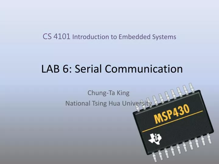
CS 4101 Introduction to Embedded Systems. LAB 6: Serial Communication . Chung-Ta King National Tsing Hua University. Introduction. In this lab, we will learn Communication peripherals of MSP430 LaunchPad How to implement a software UART on MSP430 LaunchPad

E N D
CS 4101 Introduction to Embedded Systems LAB 6: Serial Communication Chung-Ta King National TsingHua University
Introduction • In this lab, we will learn • Communication peripherals of MSP430 LaunchPad • How to implement a software UART on MSP430 LaunchPad • How to let MSP430 LaunchPad communicate with the PC through RS232 interface
Comm. Peripherals in MSP430 • Universal Serial Interface (USI): • A lightweight module handles only synchronous communication: SPI and I2C • Included in MSP430G2331 • Universal Serial Comm. Interface (USCI): • Handle almost all aspects of the communication • Asynchronous channel, USCI_A: act as a universal asynchronous receiver/transmitter (UART) to support the usual RS-232 communication • Synchronous channel, USCI_B: handle both SPI and I²C as either master or slave • Included in MSP430G2553
RecallPins for Comm P1.1 TXD P1.2 RXD
Pin Connections Use TACCR0 TXD Use TACCR1 RXD
For Transmission TXD pin For Receive RXD pin Latch allows samplingat precise time, regardless of ISRlatency
Software UART by Timer_A • Between transmissions, CCx (capture/compare) waits in the Capture mode for a falling edge on its input. • When a falling edge is detected, TACCRx captures the count in TAR and an interrupt is requested. CCx is switched to Compare mode, and TACCRx is set to fire an interrupt after 1.5 of the bit period from now. • The next interrupt occurs and SCCI contains the value of LSB. ISR saves it. Next compare event is set up to occur after a further bit period. • The above procedure is repeated until all 8 bits of data have been received.
Software UART: Transmission Use Capture/Compare Block 0 (TACCR0) • OUTMOD0: OUT0 signal is defined by OUT bit • OUTMOD2: OUT0 signal is reset when the timer counts to TACCR0 Use OUTMOD0 to send a 1, OUTMOD2 for 0 OUT0
Software UART: Transmission • Initialization and preparing the byte to TX
Software UART: Receive • Initialization of Capture/Compare Block 1 P1.2
Sample Code (msp430g2xx3_ta_uart9600) • Software UART, using Timer_A, 9600 baud, echo, full duplex, SMCLK at 1MHz • Main loop readies UART to receive one character and waits in LPM3 with all activity interrupt driven. • TACCR0 and TACCR1 may interrupt at any time and in an interleaved way
Sample Code (msp430g2xx3_ta_uart9600) Waken up byTimer_A1_ISR
Sample Code (msp430g2xx3_ta_uart9600) Wake up main loop 22
Setting PC for Serial Comm. • In the Debug perspective of CCS IDE, click [View] -> [Other…] and, in the Show View window, click the + next to Terminal. • Select Terminal below that and click OK.
Setting PC for Serial Comm. • A Terminal pane will appear on your screen. Click the Settings button in the Terminal pane and make the selections (set the serial communication setting)
Basic Lab • Modify the full-duplex sample code to a half-duplex UART that receives characters 0 or 1 from the PC. Turn on the green LED if a 1 is received, the red LED if a 0 is received, and no LED for other characters. Use 4800 baud, 8-bit of data, and 2 stop bits. Please check the two stop bits for correct transmission.
Bonus • Temperature Sensing System • MSP430 reads temperature from ADC every second and compare reading with the one sensed in previous second. • If the current temperature is higher, turn on the red LED and send HI to PC • If the current temperature is lower, turn on the green LED and send LO to PC • If the sensed temperature is equal to the first one turn off both LEDs and send IN to PC • Hint: • Use Timer_A alternatively for timing 1 sec and UART