Download

1 / 60
960 likes | 1.54k Views
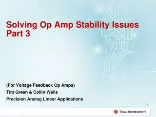
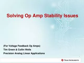
Solving Op Amp Stability Issues Part 2. (For Voltage Feedback Op Amps) Tim Green & Collin Wells Precision Analog Linear Applications. Stability Tricks and Rules-of-Thumb. Loop Gain Bandwidth Rule: 45 degrees for f < fcl. Aol β ( Loop Gain) Phase Plot.

E N D
Solving Op Amp Stability IssuesPart 2 (For Voltage Feedback Op Amps) Tim Green & Collin Wells Precision Analog Linear Applications
Loop Gain Bandwidth Rule: 45 degrees for f < fcl Aolβ (Loop Gain) Phase Plot Loop Stability Criteria:< -180 degree phase shift at fcl Design for: < -135 degree phase shift at all frequencies < fcl Why?: Because Aol is not always “Typical” Power-up, Power-down, Power-transient Undefined “Typical” Aol Allows for phase shift due to real world Layout & Component Parasitics Prevent excessive ringing due to phase margin dip near fcl
Frequency Decade Rules for Loop Gain For 45O Phase Buffer away from 180O Phase Shift • Loop Gain View: Poles: fp1, fp2, fz1; Zero: fp3 • Rules of Thumb for Good Loop Stability: • Place fp3 within a decade of fz1 • fp1 and fz1 = -135° phase shift at fz1 • fp3 < decade will keep phase from dipping further • Place fp3 at least a decade below fcl • Allows Aol curve to shift to the left by one decade Note locations of poles in zeroes in Aol and 1/β plots
Frequency Decade Rules for Loop GainPhase Plot Prediction At fcl: Phase Shift = 135O Phase Margin = 45O Note locations of poles in zeroes in Aol and 1/β plots
Op Amp Circuits & Second Order Systems Most Op Amp Circuits are adequately analyzed, simulated, and real world tested using well-known second order system response behavior. Most Op Amps are dominated by Two Poles: Aol curve shows a low frequency pole, fp1 Aol curve also has a high frequency pole, fp2 Often fp2 is at fcl for unity gain This yields 45 degrees phase margin at unity gain
Closed Loop Peaking in AC Frequency Sweep vs Phase Margin * * Phase Margin: Measure closed loop AC peaking in dB Find dB peaking on graph above and read closest damping ratio, z Use damping ratio, z, to find phase margin using Slide 75 graph From: Dorf, Richard C. Modern Control Systems. Addison-Wesley Publishing Company. Reading, Massachusetts. Third Edition, 1981.
Transient Real World Stability Test • Test Tips: • Choose test frequency << fcl • “Small Signal” AC Output Square Wave (1kHz usually works well) • Adjust VIN amplitude to yield output <50mVpp • Worst case is usually when VOffset = 0 Largest Op Amp RO (IOUT = 0) • Use VOffset as desired to check all output operating points for stability • Set scope = AC Couple & expand vertical scope scale to look for amount of overshoot, undershoot, ringing on VOUT small signal square wave • Use X1 Scope Probe on VOUT for best resolution
2nd Order Transient Curves * 25% * * Phase Margin: Measure closed loop transient overshoot (%) Find overshoot on graph above and read closest damping ratio, z Use damping ratio, z, or Overshoot (%) to find phase margin using Slide 75 graph From: Dorf, Richard C. Modern Control Systems. Addison-Wesley Publishing Company. Reading, Massachusetts. Third Edition, 1981.
2nd Order Damping Ratio, Overshoot, Phase Margin Overshoot = 40%, Phase Margin = 30 degrees Start at % Overshoot on x-axis Read up to “Damping Ratio” on “Percent Maximum Overshoot” curve Read Across to Damping Ratio on y-axis Use Damping Ratio to read across to “Phase Margin” curve.
When RO is really ZO!! OPA627 has RO OPA2376 has ZO Inductive Capacitive Resistive OPA2376 OPA627 Resistive Note:Some op amps have ZO characteristics other than pure resistance – consult data sheet / manufacturer / SPICE Model
Summary for Stability For Stability Loop Gain Analysis all we need is: Aol – from op amp data sheet or macromodel 1/b– basic by application, modified for stability Z_Load – given by application Zo – Op Amp open loop, small signal AC output impedance from op amp data sheet or macromodel Stability General Comments: Stability by modifying 1/b will decrease closed loop bandwidth Stability compensation can slow large signal response (charging of caps) – check it Simulate AC Transfer function (Closed Loop AC Response) as final check Simulate Small Signal Transient Response as final check DC operation in the lab does not guarantee stability Marginal stability can cause undesired overshoot and ringing DC circuits can get real world transient inputs from supplies, inputs, or output That ringing in your circuit is not your Grandmother’s dial telephone
Acknowledgements A special thanks to Jerald Graeme, whom we honorably dub “The Godfather of 1/b” for his work at Burr-Brown Corporation in research and writing about Op Amp Stability using 1/b. Jerald Graeme Brief Biography: From: http://electronicdesign.com/analog/jerald-graeme When ICs and op amps were separate devices, Jerald Graeme was among the first to develop a combined IC op amp while at Burr-Brown, in a 1968 team effort with Motorola. He designed many more op amps and video amplifiers whose precision, high speed, or low drift amplification made them a very useful component in a variety of analog applications. Nine U.S. patents and numerous foreign counterparts resulted from these designs. The internationally acknowledged authority on electronic amplifiers wrote five very popular books about op amps, the latest being Photodiode Amplifiers: Op Amp Solutions and Optimizing Op Amp Performance. The latter, subtitled "A new approach for maximizing op amp behavior in circuit designs without extensive mathematical analysis," offers design equations and models that reflect real-world op amp behavior and makes analysis of difficult-looking configurations easy. Graeme's earlier books are: Op Amps: Design and Application, Designing with Operational Amplifiers, and Amplifier Applications of Op Amps. He expects signal processing with op amps to be the domain of digital devices, but they will still require an analog interface to integrate with real-world items like process control or avionics. Jerald Graeme Books: http://www.amazon.com/Jerald-G.-Graeme/e/B001HO9X60
Acknowledgements Op Amp Stability Series Tim Green, Senior Analog Applications Engineer Texas Instruments http://www.en-genius.net/site/zones/acquisitionZONE/technical_notes/acqt_050712
Appendix Index Op Amp Output Impedance Pole and Zero: Magnitude and Phase on Bode Plots Dual Feedback Paths and 1/b Non-Loop Stability Problems Stability: Riso (Output Cload) Stability: High Gain and CF (Output Cload) Stability: CF Non-Inverting (Input Cload) Stability: CF Inverting (Input Cload) Stability: Noise Gain Inverting & Non-Inverting (Output Cload) Stability: Noise Gain and CF (Output Cload) Stability: Output Pin Compensation (Output Cload) 12) Stability: Riso w/Dual Feedback (Output Cload) – Zo, 1/b, Aol Technique 13) Stability: Discrete Difference Amplifier (Output Cload)
1) Op Amp Output ImpedanceOpen Loop (ZO) & Closed Loop (ZOUT)
Op Amps and “Output Resistance” Definition of Terms: RO= Op Amp Open Loop Output Resistance ROUT= Op Amp Closed Loop Output Resistance ROUT = RO / (1+Aolβ) From: Frederiksen, Thomas M. Intuitive Operational Amplifiers. McGraw-Hill Book Company. New York. Revised Edition. 1988.
Derivation of ROUT (Closed Loop Output Resistance) 1) b = VFB / VOUT = [VOUT (RI / {RF + RI})]/VOUT = RI / (RF + RI) 2) ROUT = VOUT / IOUT 3) VO = -VE Aol 4) VE = VOUT [RI / (RF + RI)] 5) VOUT = VO + IOUTRO 6) VOUT = -VEAol + IOUTROSubstitute 3) into 5) for VO 7) VOUT = -VOUT [RI/(RF + RI)] Aol+ IOUTRO Substitute 4) into 6) for VE 8) VOUT + VOUT [RI/(RF + RI)] Aol = IOUTRO Rearrange 7) to get VOUT terms on left 9) VOUT = IOUTRO / {1+[RIAol/(RF+RI)]} Divide in 8) to get VOUT on left 10) ROUT = VOUT/IOUT =[ IOUTRO / {1+[RIAol / (RF+RI)]} ] / IOUT Divide both sides of 9) by IOUT to get ROUT [from 2)] on left 11) ROUT = RO / (1+Aolβ)Substitute 1) into 10) ROUT = RO / (1+Aolβ)
ROUT vs RO • RO does NOT change when Closed Loop feedback is used • ROUT is the effect of RO, Aol, and β controlling VO • Closed Loop feedback (β) forces VO to increase or decrease as needed to accommodate VO loading • Closed Loop (β) increase or decrease in VO appears at VOUT as a reduction in RO • ROUT increases as Loop Gain (Aolβ) decreases
When RO is really ZO!! OPA627 has RO OPA2376 has ZO Inductive Capacitive Resistive OPA2376 OPA627 Resistive Note: Some op amps have ZO characteristics other than pure resistance – consult data sheet / manufacturer
Some Data Sheets Specify ZOUT NOT ZO Recognize ROUT instead of RO: ROUT inversely proportional to Aol ROUT typically <100W at high frequency This is really ZOUT or ROUT! TLC082 TLC082 1 3 2 2 3 1
Some Data Sheets Specify ZOUTNOT ZO TLC082 1 2 3
Spice Compared with Calculated Analysis SPICE AC Analysis: For best accuracy use highest resolution i.e. maximum “Number of Points” Note: 1) SPICE analysis accounts for loop gain effects and closed loop phase shifts due to op amp Aol. 2) Calculated results do not account for loop gain effects and closed loop phase shifts due to op amp Aol.
Closed Loop Gain: Magnitude and Phase SPICE Ideal Op Amp & Poles: Equivalent Circuit Note: 1) SPICE - Ideal Circuit analysis matches Calculated results. 2) No loop gain effect or closed loop phase shifts due to op amp Aol.
Closed Loop Gain: Magnitude and Phase SPICE Ideal Op Amp & Poles: Equivalent Circuit
Dual Feedback and 1/β Concept Analogy: Two people are talking in your ear. Which one do you hear? The one talking the loudest! Dual Feedback:Op amp has two feedback paths talking to it. It listens to the one that feeds back the largest voltage (β = VFB / VOUT). This implies the smallest 1/β! • Dual Feedback Networks: • Analyze & Plot each FB#? 1/β • Smallest FB#? dominates 1/β • 1/β = 1 / (β1 + β2) • 1/β relative to VO • Note: VO = Op Amp Aol Output before • Ro for this Dual Feedback Example
Dual Feedback and 1/β How will the two feedbacks combine? Answer: TheLargest β(Smallest 1/β)will dominate! Small 1/β Large 1/β
Dual Feedback and the BIG NOT WARNING:This can be hazardous to your circuit! • Dual Feedback and the BIG NOT: • 1/β Slope changes from +20db/decade to -20dB/decade • Implies a “complex conjugate pole ” in the 1/βPlot with small damping ratio, ζ. • Implies a “complex conjugate zero” in the Aolβ (Loop Gain Plot) with small damping ratio, ζ. • +/-90° phase shift at frequency of complex zero/complex pole. • Phase slope from +/-90°/decade slope to +/-180° in narrow band near frequency • of complex zero/complex pole depending upon damping ratio, ζ. • Complex zero/complex pole can cause severe gain peaking in closed loop response.
Complex Conjugate Pole Phase Example From: Dorf, Richard C. Modern Control Systems. Addison-Wesley Publishing Company. Reading, Massachusetts. Third Edition, 1981.
Dual Feedback and 1/β Example Dual Feedback: FB#1 through RF forces accurate Vout across CL FB#2 through CF dominates at high frequency for stability Riso provides isolation between FB#1 and FB#2
Zo External Model for Dual Feedback Analysis Zo External Model: VCV1 ideally isolates U1 so U1 only provides data sheet Aol Set Ro to match measured Ro Analyze with unloaded Ro (largest Ro) which creates worst instability Use 1/β on Aol stability analysis 1/β, taken from VOA will include the effects of Zo, Riso and CL
Dual Feedback, FB#1 And FB#2 FB#1 FB#2 FB#1 and FB#2 1/ β Analysis: There is only one net voltage fed back as β to the -input of the op amp β_net = β_FB#1 + β_FB#2 This implies that the largest β will dominate → smallest 1/ β will dominate Analyze FB#1 with CF = open since it will only dominate at high frequencies Analyze FB#2 with CL = short since it is at least 10x CF
Dual Feedback and 1/β – Create the BIG NOT BIG NOT BIG NOT 1/b: At fcl rate-of-closure rule-of-thumb says circuit is stable but is it?
Dual Feedback and 1/β – Create the BIG NOT BIG NOT Loop Gain: Loop Gainphase shift >135 degrees (<45 degrees from 180 degree phase shift) for frequencies <fclwhich violates the loop gain phase buffer rule-of-thumb. But is it stable?
Dual Feedback and 1/β – Create the BIG NOT BIG NOT Transient Stability Test: Excessive ringing and marginal stability are apparent. Real world implementation and use may cause even more severe oscillations. We do not want this in production!