Download
1 / 12
120 likes | 123 Views
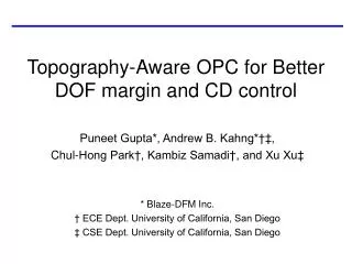
Topography-Aware OPC for Better DOF margin and CD control. Puneet Gupta*, Andrew B. Kahng*†‡, Chul-Hong Park†, Kambiz Samadi†, and Xu Xu‡ * Blaze-DFM Inc. † ECE Dept. University of California, San Diego ‡ CSE Dept. University of California, San Diego. Motivation.

E N D
Topography-Aware OPC for Better DOF margin and CD control Puneet Gupta*, Andrew B. Kahng*†‡, Chul-Hong Park†, Kambiz Samadi†, and Xu Xu‡ * Blaze-DFM Inc. † ECE Dept. University of California, San Diego ‡ CSE Dept. University of California, San Diego
Motivation • The depth-of-focus variation corresponding to thickness variation severely affects the metal patterning of the subsequent upper layer • Standard OPC (SOPC) assigns zero defocus for each layer which will lead to CD variation of the metal feature that will be placed on that layer • Topography-aware OPC (TOPC) will compensate for thickness variation and will adjust the OPC and ORC accordingly
CD variation by topography (a) Side view showing thickness variation over regions with dense and sparse layout. (b) Top view showing CD variation when a line is patterned over a region with uneven wafer topography, i.e., under conditions of varying defocus. New OPC technique that is aware of post-CMP topography variation is required
0.0 DOF -0.3 DOF (a) (b) Original metal Resist Image OPC layer 0.0 DOF -0.3 DOF (c) (d) SOPC Simulation Results • Original layout and simulation result with zero DOF model • Original layout and simulation result with -0.3umDOF model in the non-planar topography • Standard OPC layout and simulation result with zero defocus model • Standard OPC layout and simulation result with -0.3umDOF model in the non-planar topography SOPC cannot compensate CD variation induced by topography!!
The following table shows four different combinations of OPC and ORC (STD, and T-A stands for Standard and Topography-aware methodologies, respectively) STD OPC/ORC will generate a small CD error, but the premise of this method is at fault STD-OPC/T-A-ORC combination yields a large CD error and hence not desirable. T-A-OPC/STD-ORC combination does not make sense! T-A-OPC/T-A-ORC yields a small CD error and considers layers with uneven topography Standard vs. Topography-Aware OPC and ORC
K-DML Assignment Problem • Always try to assign one feature to DML partition according to its height • However, assign two features within the distance of R to different DML Partition will result in Optical Error • Objective: Partition of all features into k DMLs to minimize the number of optical errors Distance < R Modified Assignment Assignment according to height
k-DML Assignment Algorithm • Compute the post-CMP topography and the height for each feature • Construct a network flow topology with vertex v for each feature and an edge between two close vertices • for (i = 1; i < k; i++) • Calculate edge capacitances • Solve the maximum S-T flow problem • All vertices on the S side of the cut are assigned to DML i 1 10 S T Max flow =1 Min cut =1
Standard OPC Flow Library & Technology SOPC GDSII SOPCed GDSII CMP Simulation DOF Model Database DOF Marking Layer TOPC Input GDSII for TOPC TOPCed GDSII TOPC Flow • A map of thickness variation from CMP simulation is converted to DML and then fed into GDSII for TOPC • TOPC applies different DOF models to metal lines according to DML
Experimental Setup • Sigma-C’s Solid-C • Check CD of metals on topography • Mentor’s OPCpro • TOPC, SOPC and ORC (Optical Rule Check) • Cadence SOC Encounter • Placement & Route • Synopsys Design Complier • Synthesis
DOF Enhancement • Evaluate DOF margin at a test pattern • TOPC enhances DOF margin as topography thickness has over 0.2µm • Total DOF range of TOPC at 0.2um is increased by 0.14um compared to SOPC Method Topography: thickness (µm) • directional • DOF range • (µm) + directional DOF range (µm) SOPC 0.0 0.25 0.25 0.1 0.35 0.15 0.9 0.2 0.45 0.05 0.3 0.48 0.0 TOPC 0.0 0.25 0.25 0.1 0.38 0.18 0.2 0.52 0.12 Test pattern : 0.14µm W/ 0.9µm S 0.3 0.49 0.09
EPE Reduction • EPE is evaluated by alu128 testbed from Artisan TSMC 0.09µm • CASE I: assume the stepper machine focuses on the average of the topography ( Focus on DML1 ) • CASE II: assume the stepper machine focuses on DML2 DOF (µm) TOPC (µm) TORC (µm) DML 2 1 0 0.13 0.13 0.26 0.0 0.0 0.13 -0.13 -0.13 -0.26 CASE I TOPC (µm) TORC (µm) DOF (µm) DML 0.0 0.0 0.13 -0.13 -0.13 -0.26 -0.26 -0.26 -0.39 2 1 0 CASE II
Conclusions and Ongoing works • Conclusions • The novel methodology for wafer-topography aware OPC is proposed • For 90nm foundry library, TOPC achieves up to 75% reduction of EPE at worst-case defocus • Ongoing works • Investigate the impact of a CD error reduction on RC parasitics of the circuit • Study new DML assignment to reduce the CD error at boundary of DMLs