Download
1 / 18
180 likes | 403 Views
Muon Detector Jiawen ZHANG. Introduction The Detector Choices Simulation The structure and detector design The Expected performance Schedule. BESII m detector. Worked for 12 years Leakage problem Large size (5 × 6cm ) Signal too slow

E N D
Muon DetectorJiawen ZHANG • Introduction • The Detector Choices • Simulation • The structure and detector design • The Expected performance • Schedule
BESII m detector • Worked for 12 years • Leakage problem • Large size (5×6cm ) • Signal too slow Signal drift time is about 0 ~700ns, and the trigger signal delay is about 2.4ms • Solid angle (~63% )
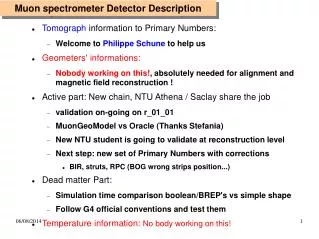
BESIII m Detector • Them detector is the outmost subsystem of the BESIII detector. It includes detectors and hadron absorbers. Its main function is to identify muons from pions and other hadrons in the momentum range of 0.4—1.5GeV/c and to provide the solenoid flux return
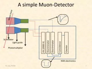
The Detector Choices Two possible kinds of detectors • The Plastic Streamer Tubes (PST) • The Resistive plate counters (RPC) RPC and PST are very similar, such as graphite painting, induced strips, gas mixture etc.
The Resistive plate counters (RPC) Advantages • Small dead region • Fast response • Lower cost • No poisonous material in case of fire Shortcoming • Very high voltage (8000V), easy to produce sparks • No experience
The Plastic Streamer Tubes (PST) • Larger signal pulse, good signal noise ratio Taking ALEPH m detector as an example • Typical strip signals around 6 mV (at BESIII m detector, the strips are shorter than ALEPH, so the signal maybe larger than 6 mV ) • Rise time 10 ns and width at the base ~ 100ns • Have a rather long plateau • Stable operation , ALEPH has stop working, however the PST still works very stably • More experience At IHEP, Beijing, some people ever made many PSTs for ALEPH
Simulation Careful simulation studies were made for initial designing and optimizing • Geant 3.21 • Condition • 13 radiation lengths BGO, • all of the other inner detectors equal to 6cm Fe plate
m detection efficiency and p contamination Increase the position pricisoin, considering the p interaction with Fe which can produce second class of particles, and, in turn, produce more than one hit, the p contamination can be reduced in the low momenta Efficiency % Radial thickness of Fe (cm)
m hits position distribution Hits position s The sigma of the hit position distribution of moun will be about 4 to 8cm after moun’s multiple scatters in the absorber Fe. In this case, improving the position distinguish will not help the separation of moun and pion well but increasing the electronic channels and cost. Radial thickness of Fe (cm)
The structure and detector design Requirements lHigh detection efficiency for muons. lLarge solid angle coverage. l Wide momentum range (the minimum momentum ~400MeV). lHigh rejecting factor for other charged particles. l Suitable position precision.
Structure of PST • Similar to ALEPH’s • Each cell has an inner dimension of 0.9×0.9cm2, The internal surface of comb is painted with graphite . • consists of plastic (PVC) comb profile having 9 cells each • Wires diameter 100 mm • Strips on the two side of the streamer tubes(x—strips and y—strips) or one view only
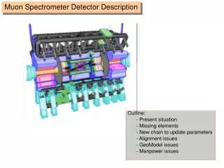
General structure • Sandwiched structure with Fe as absorber material and PST • The barrel counters are subdivided into 8 sectors, and 12 layers • inner radius is ~1.5m and outer radius is about ~2.5m • Length 3.6m • 11 layers Fe 2, 2, 2, 3, 3, 4, 4, 6, 6, 8 and 10cm (Total thickness 50cm)
End cap m counter • Each end cap m counter is divided 4 pieces Each end, the 4 pieces are separated to two parts and supported at left and right and each part has its own railway for moving • 12 layers of PSTs
Gas select • ALEPH (12.5%Ar +56.5% CO2 + 30% C4H10) Expensive and inflammable long plateau • BESII ESC (40%Ar + 60%CO2) cheap and safe short plateau Need some R&D
The Expected performance • 0.4GeV/c may be the low momentum limit to identify m • cos q ~0.90 • efficiency >95%
m detection efficiency and contamination from p versus momentum m Efficiency Good m/p separation can be obtained with momenta greater then 0.6GeV/c. With momenta less then 0.5GeV/c, the separation becomes worse. And with momenta less then 0.4GeV/c, the m efficiency is rather lower. So 0.4GeV/c may be a low momentum limit to identify m. p contamination Momentum GeV
Read out channels • Strips on the two side of the streamer tubes(x—strips and y—strips). Strips wide 3cm Barrel 120×8×12+55×8×12=11520+5280=16800 End cap 82×2×4×2×12=15744 Total 16800+15744≈ 32500 • One side view only Barrel 55×8×12=5280 End cap 82×2×4×12=7872 Total 5280+7872≈ 13100 Outer layers use wide strips, can reduce some channels
Schedule • 2001,Oct.—2003,May:R&D, Design and Lab. construction. • 2003,Jun.—2005,Oct.:Chamber production and test. • 2005,Nov.—2006,May:Installation.