Download
1 / 11
140 likes | 309 Views
Creating 3D Renderings and Camera Shots – Revit Architecture. Preparing Renderings of a 3D view for PowerPoint. There are two output setting options when rendering: Screen Printer

E N D
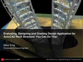
Creating 3D Renderings and Camera Shots – Revit Architecture
Preparing Renderings of a 3D view for PowerPoint There are two output setting options when rendering: Screen Printer Screen renders are a lower quality that are used for displaying images on a screen. When viewing images on a computer, an image can have a much smaller resolution size and still not have a discernible difference compared to a render for printing. Print renders use what’s called DPI. (dots per inch) This is different than a term you might have heard before-PPI. The higher the DPI, the better tonality the image will have once printed and the longer it will take to render and print. Because of the quality difference, print renders in general take a lot more time than screen renders. Also, as far as Revit is concerned, the greater the DPI, the larger the size of the image will be. If you want to make large size image prints, a greater amount of DPI will benefit you. You may not be able to tell the difference here, but compare the two on the printed out example I have in class. Click here for more info about the difference between DPI and PPI Screen Render (Med) Print Render (Med 150 DPI)
SCREEN RENDER • Select the view that you want to render • Hide anything that does not need to be in the view – this reduces Rending Time • Zoom into and crop only the region you want to illustrate • Click on the Rendering Dialog icon at the bottom of your screen • Select the Quality of Rendering (Better quality = more time) • To right are examples of a Medium and High Quality Rendering • Select a Lighting Scheme and Sun setting • Select a Background • ClickRender and wait…… • Then Click on Save to Project 6 3 Remember this # There really isn’t much of a difference between Medium and High, but a much larger difference when you go with Best (Tradeoff= takes much longer) 4 5 MEDIUM 7 HIGH
PRINTER RENDER • Select the view that you want to render • a. Hideanything that does not need to be in the view – this reduces Rending Time • b. Zoominto and crop only the region you want to illustrate • Click on the Rendering Dialog icon at the bottom of your screen • Select the Quality of Rendering (Better quality = more time) • Switch Resolution to Printer and choose a DPI • Select a Lighting Scheme and Sun setting • Select a Background • ClickRender and wait…… • Then Click on Save to Project 7 3 4 Remember this # 5 6 8
Exporting Images for PowerPoint Select your saved rendering from the Project Browser Go to the Application Button and select Export/Images/Image To export the image make sure your setting match the example shown here Change the Output location and name to your CAD II/GEP folder From this point you just need to Insert/Image in PowerPoint and navigate to the file you created This number should be whatever the number was that I said you should remember earlier in the PPT
Preparing Renderings using the Camera View Navigate to a floor plan where you want to create a Camera View Click on 3D View/Camera
Preparing Renderings using the Camera View • Select a starting Point of view for the Camera (click on the screen) • Notice the Options Bar • Check the Perspective Box • Edit the level of Offset for the Camera • Select the Level you want to view from • Drag and drop the grip to create the Perspective View
Preparing Renderings using the Camera View Change your Model Graphics Style to Shading w/ Edges Notice that 3D View 1 has now been created under 3D Views in your browser Export this image so you can insert it onto your PowerPoint
Preparing Renderings using the Camera View Control Grips can be used to expand the Crop Region If you go back to the floor plan you can edit the angle of the camera view and it will update your 3D automatically Original 3D View Floor Plan 1 – with camera grips 3D View adjusted
Edit your view using the Navigation Wheel You can use the Navigation Wheel and all the options to Pan, Zoom, or Orbit your view. Original 3D View New 3D View
Creating a Rendering from a Camera Shot You can also change perspectives in the properties panel: If you click on the border around the 3D View. You can click on which will allow you to change the physical dimensions of the image.