Download

1 / 1
10 likes | 260 Views
New approach in functionality and testing for HV Capacitor Bank Protection Jorge Cardenas † (J.C.), Sean Cox ♣ (S.C), Petru van Wyk ♣ (P.W.), Boitumelo Chaka * (B.C), Mzwakhe Msimango * (M. M.), Mietek Klimek * (M. K.), Anura Perera (A. P.)

E N D
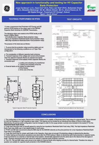
New approach in functionality and testing for HV Capacitor Bank Protection Jorge Cardenas† (J.C.), Sean Cox♣ (S.C), Petru van Wyk♣ (P.W.), Boitumelo Chaka* (B.C), Mzwakhe Msimango* (M. M.), Mietek Klimek* (M. K.), Anura Perera (A. P.) GE Digital Energy†, Powertech IST Energy♣, Eskom* Spain†, South Africa♣* TEST CIRCUITS TESTINGS PERFORMED IN RTDS 1.It was a requirement that Powertech IST Energy and GE perform RTDS testing on the relays used in the CBP002 Capacitor Bank Schemes for ESKOM Transmission. The following relays were tested at the RTDS facility at GE based in Bilbao Spain: · C70 (Multifunction Capacitor Bank protection relay) · T60 (Low Impedance Restricted Earth Fault protection relay) · MIB (High impedance Restricted Earth Fault protection relay) The purpose of the tests was as follows: 1. To prove that the protection relays would be stable and not mal-operate for the following conditions on a C-Type Filter configuration: a. The energisation of different capacitor bank schemes. b. Transient response of the voltage and current at the busbars when the adjacent Capacitor Banks are opened and closed. c. Transient response at the busbars where Capacitor Banks are connected upon i. Loading and unloading of a transformer ii. Loading and unloading of the line d. External faults on the system as listed below: i. At the Busbar ii. At the end of the line Conclusions Typical Capacitor Bank Protection System Internal Faults simulated in the Test Circuit 4 CONCLUSIONS 1. The configuration of the surge arrestors have a large impact on the stability of Restricted Earth Fault relays for external faults. This is relevant for both low impedance or high impedance type relays. This tripping can be avoided by an intentional time delay of 50ms on both relays. Alternatively, the primary plant configuration must be changed in order for the surge arrestor currents to be included in the neutral CT for the Restricted Earth Fault circuit. 2. It was seen that there was no benefit gained by using the low impedance Restricted Earth Fault relay (T60). The high impedance Restricted Earth Fault relay (MIB) was in fact slightly faster in most cases. 3. PT-IST and GE both recommend using the MIB relay for the ESKOM networks as the price premium for a low impedance Restricted Earth Fault relay is not justified. 4. It was also found that for certain earth faults in the Capacitor, there was not enough V0 polarizing voltage to determine the direction. 5. Further testing and theoretical calculations were done after the RTDS testing in Spain on directional earth fault protection in capacitor banks. It was found that for an external or internal fault at the busbars, directionality appeared to be the same due to the nature of the two types of faults. Therefore directional earth fault cannot be utilized in capacitor bank protection schemes. 6. The C70, T60 and MIB relays were proven to be stable for external faults while tripping correctly for internal faults. Therefore the relays in question are suitable for capacitor bank protection in the ESKOM network..