Download

1 / 15
150 likes | 287 Views
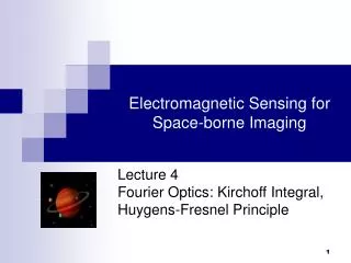
Electromagnetic Sensing for Space-borne Imaging. Lecture 5 Finite Apertures, Diffraction Limits, and Far-Field Intensity Patterns. Analysis of Finite Apertures. Limitations Due to Diffraction : What portion of the field distribution on I is actually received by the finite aperture?. I.

E N D
Electromagnetic Sensing for Space-borne Imaging Lecture 5Finite Apertures, Diffraction Limits, and Far-Field Intensity Patterns
Analysis of Finite Apertures Limitations Due to Diffraction: What portion of the field distribution on I is actually received by the finite aperture? I Measurement signal A
Limitations Due to Diffraction - reception I Transmitted power Antenna Feed A To account for the finite aperture, first note that (1) the received signal (previous slide) is produced only by that portion of the field, , that starts from I and is able to enter A; and (2) EM wave propagation is time-reversible
Inverse H-F Principle for a Finite Aperture is the same as the field on I that we would get by propagating backwards in time, out through A and projected back to I as illustrated above. On A, the field is just U(P). Off A, it is zero. So, using the Inverse Huygens-Fresnel principle : But, likewise:
Reciprocity Transmitted power Measurement signal AQ AP
Derivation of Approximate Field Transformations zP d x I O P s z s D y Q Extended source, s The basic imaging situation. Recall: With the above situation, we then have:
Derivation of Approximate Field Transformations – Cont’d Our aim, in this section is to find approximate expression for the received and transmitted field Patterns that are appropriate for the far-field region The first step is to expand the distance function, s: Hence:
Derivation of Approximate Field Transformations – Cont’d Results for U(P) and U(Q) are: Then, using the definition of the aperture function, the field amplitude on the image plane becomes: where A is the aperture function defined earlier.
Calculating the transmitted intensity pattern from what we’ve learned so far I Transmitted power Antenna Feed A
Calculating the transmitted intensity pattern from what we’ve learned so far – The circular aperture
Intensity pattern (or point source image) from a circular aperture The intensity pattern depends only on the radial distance of the look angle from the point source direction. Almost all the energy is contained in the central Airy disk within x < , or for look angles such that: / D
Intensity pattern (or point source image) from a circular aperture Intensity distribution as would be seen without saturation. Only the central maximum is visible Intensity distribution with over 1200% saturation, so that the secondary fringes are visible.
Angular Resolution and Aperture Size Angular Resolution: The minimum angle between two point sources such that the system is able to distinguish two sources, not one. As illustrated below left, this minimum angle occurs when the maximum of the airy pattern of one source coincides with the first minimum of the Airy pattern of the second source. This means that for a circular aperture of diameter D, the resolution angle, r, is: r = 1.22 /D Therefore, for a given wavelength, the size of objects that can just be discerned is determined by the aperture diameter, D. r is also the minimum beam angle for power transmission Light from star 1 Light from star 2 Diffraction-limited, no deformations