Download
1 / 24
240 likes | 432 Views
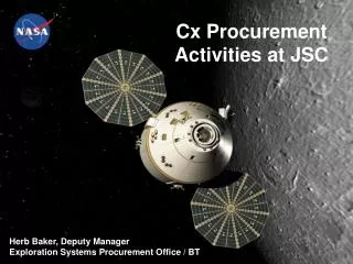
CREW EXPLORATION VEHICLE ORION LUNAR ORBIT: COMMUNICATION LINK ANALYSIS. August 3, 2009 David Huynh* LERCIP Summer Intern Systems and Networks Architecture Project (SNAP) Mentor: Kul Bhasin Alternative Mentor: Seth Matthews. *Rising Freshman, Ohio State University. Outline.

E N D
CREW EXPLORATION VEHICLE ORION LUNAR ORBIT: COMMUNICATION LINK ANALYSIS August 3, 2009 David Huynh* LERCIP Summer Intern Systems and Networks Architecture Project (SNAP) Mentor: Kul Bhasin Alternative Mentor: Seth Matthews *Rising Freshman, Ohio State University SCaN Systems and Networks Architecture Project Glenn Research Center
Outline • Objectives and Goals • Orion-Lunar Mission Overview • Communication Link Requirements, Drivers, and Limitations • Communications Link Analysis • Orion to Deep Space Network (DSN) Stations • Orion to Small Pressurized Rover (SPR) and Altair • Orion to Science Communication Hybrid Orbiter (SCHO) • Communication Design and Summary • Backup – Glossary SCaN Systems and Networks Architecture Project Glenn Research Center
Objectives and Goals • Objective: Project Constellation Lunar Phase • NASA Authorization Act of 2005 • Return man to moon by 2020 • Prepare for prolonged lunar stay; human settlement • Goals: SNAP • Analyze and design comm. links for lunar Sortie mission • Optimize comm. links to enable future lunar explorations • Goals: Summer Internship • Research Constellation • Become familiarized with analysis tool, Satellite Tool Kit (STK) • Establish plausible future lunar scenario • Generate analysis and design for Orion comm. links SCaN Systems and Networks Architecture Project Glenn Research Center
0. NASA (SNAP) Lunar Sortie Mission Scenario “Lunar” Earth Ground Stations MOC Science/Comm Hybrid Orbiter (SCHO) Orion In-Situ Resource Utilization (ISRU) Altair Small Pressurized Rover (SPR)
Path of Orion Goldstone, United States Madrid, Spain Orion’s Orbit: Circular Inclination – 45° Altitude – 500 km Period– ≈ 1.92 hrs Canberra, Australia SCaN Systems and Networks Architecture Project Glenn Research Center
Orion: General Overview • Crew Module (CM) • Pressurized crew and cargo transport • Only component that returns to Earth for potential re-use. Size Total Liftoff mass: Lunar – 29,952 kg ISS – 27,231 kg Diameter: 5.5 m (16.5 ft) Volume: 10.8 m3 (380 ft3) 80% larger than Apollo Thrust System Main thrust: 7,500 lbs of force Monomethyl hydrazine (MMH) + nitrogen tetroxide (N2O4) Orientation/Attitude control: 24 smaller engines; 125 lbs of force each Power System Two Solar Arrays: Diameter: 5 m (16 ft) Provide 9 kW of power • Service Module (SM) • Propulsion, electrical power, and fluids storage 5’ 9” SCaN Systems and Networks Architecture Project Glenn Research Center
Orion: International Space StationScenario Communications • High Gain Antenna: • Diameter – 0.75 m • Depth – 0.5334 m • Power – 7.1 W • Frequency: • Transmit – 2.25 GHz • Receive – 2.106 GHz *HGA based on previously established parameters *Omni directional antenna modeled using Cx Master Link Book High-gain antenna SCaN Systems and Networks Architecture Project Glenn Research Center
Link Requirements • Level 0: Orion shall transmit to and receive from the SPR, the SCHO, and the Altair when in the proper orbit window • Level 1: Orion shall transmit to and receive from the SPR, the SCHO, and the Altair when in the proper orbit window: • at S-band • at a maximum data rate of 192 kbps • with a BER less than or equal to 10-8 • *Necessary requirements for • digital voice, video, and file transfer SCaN Systems and Networks Architecture Project Glenn Research Center
Orion Communication Architecture/Comm Link Analysis Goldstone Madrid Canberra • Orion Omni – SPR • Data Rate • Uplink link margin: 20.2 dB • Downlink link margin: 10.3 dB • Due to Orion’s orbit: • -Total access: ≈ 2.5 hrs per Earth day • -Broken into 11 smaller access windows, each an average of 13.5 min • Orion HGA – DSN 18m • Data Rate: 0.1862 mbps • Uplink link margin: 12.1 dB • Downlink link margin: 17.7-18.0 dB • Access Times: • Goldstone ≈ 4.7 hrs per Earth day • Madrid ≈ 11.4 hrs per Earth day • Canberra ≈ 1.7 hrs per Earth day • Due to Orion’s orbit: • -Total access: ≈ 2.5 hrs per Earth day • -Broken into 11 smaller access windows, each an average of 13.5 min • Orion Omni – SCHO • Data Rate: 0.1862 mbps • Uplink link margin: -1.7 dB* • Downlink link margin: -11.8 dB* • *Due to different orbits, access times and separation distances are very unfavorable • Orion – Altair • Data Rate: 0.1862 mbps • Uplink link margin: 20.2 dB • Downlink link margin: 10.4 dB There are sporadic pockets of time during which acceptable comm link can be established, such as: 10:31-11.29pm, June 28 (≈ 1 hr) Eb/No {4.9 dB, 1.7 dB} This comm link to be used as emergency link Tx power: 200W Tx: 7.1 W DSN SmallPressurizedRover(SPR) Tx power: 7.1W Tx: 7.1 W Tx: 75 W Altair Tx: 75 W Orion Tx: 75 W Tx: 5.0 W Science Communication Hybrid Satellite (SCHO)
Orion: Communication Design • Omni-Directional Antenna: • Gain – 4-8 dB • Power – 26.3 W • Frequency: • Transmit – 2.25 GHz • Receive – 2.25 GHz • High Gain Antenna: • Diameter – 0.75 m • Depth – 0.5334 m • Power – 7.1 W • Frequency: • Transmit – 2.25 GHz • Receive – 2.106 GHz
Summary Orion – DSN 18m: Madrid has largest window of access time (≈11.4 hrs) Orion – SPR & Altair: Due to Orion’s low altitude orbit, access times are severely limited (≈13.5 min windows); should be secondary option for SPR & Altair communications, if direct DSN link not possible Orion – SCHO: Due to differing orbits, access times are both sporadic and limited; with occasional 1 hr windows of acceptable Eb/No, link should only be used as emergency communications *STK capabilities greatly increase efficiency with which engineers can be familiarized with communication analysis SCaN Systems and Networks Architecture Project Glenn Research Center
Thank You To!… Mentors: Kul Bhasin, Seth Matthews, Brian Barritt, Wes Eddy, Bert Golden, Janice Haas, Eric Knoblock, Joe Warner Intern Team:Kevin Bhasin, Rachel Coulter, Nick Iaconis, Devin Schwab, Katie Trase Background Information Providers: Chuck Sheehe
Glossary • Project Constellation – a human spaceflight program within NASA which determines how NASA will pursue the goals laid out in the Vision for Space Exploration and the NASA Authorization Act of 2005 • Systems and Architecture Project – Lunar Experience (SNAP-LE) • Orion – an Apollo-based spacecraft designed to be the service module for two to four astronauts for NASA missions • DSN Stations – an international network of communication facilities that supports interplanetary spacecraft missions, and radio and radar astronomy observations for the exploration of the solar system and the universe; best known for its large antennas • Small Pressurized Rover – (SPR) vehicle that provides a shirt sleeve work environment, emergency shelter, and long distance transportation on the lunar surface for astronauts • Science Communication Hybrid Orbiter – (SCHO) a hybrid lunar satellite in a lunar orbit, both performing scientific research/data gathering and acting as a relay satellite; the goal of the relay satellite mission will be to reduce the user burden for other lunar systems • Altair – previously known as the Lunar Surface Access Module (LSAM); the lander spacecraft component of NASA’s Project Constellation; will carry astronauts to the lunar surface for lunar sortie and lunar outpost missions
Glossary (Continued) • Omni-Directional Antenna – an antenna system which radiates power uniformly in one plane with a directive pattern shape in a perpendicular plane • High Gain Antenna – (HGA) an antenna with a focused, narrow radiowave beam width; allows more precise targeting of the radio signal; a.k.a. a directional antenna • Antenna Gain – relates the intensity of an antenna in a given direction to the intensity that would be produced by a hypothetical ideal antenna that radiates equally in all directions (isotropically) and has no losses; usually measured in dimensionless unit of dB • S-band – frequency range between 2-4 GHz • Data rate – the number of bits that are conveyed or processed per unit of time • Bit Error Rate/Ratio – (BER); the ratio of the number of bits, elements, characters, or blocks incorrectly received to the total number of bits, elements, characters, or blocks sent during a specified time interval • Eb/No – Signal to noise ratio; the measure of signal to noise ratio for a digital communication system; measured at the input to the receiver and is used as the basic measure of how strong the signal is
Orion Omni Directional Antenna Block Diagram Antenna Sub-system RF Equipment Orion Omni Directional Communication Payload Design Communications Equipment Orion Comm. Control Version01 (July 20, 2009)
Orion High Gain Antenna Block Diagram Antenna Sub-system RF Equipment Orion High Gain Communication Payload Design Communications Equipment Orion Comm. Control Version01 (July 20, 2009)
Link Budget Analysis Orion to Goldstone18m Calculated based off Orion’s set parameters (diameter and power) Values taken from Cx Master Link Book Results computed by Satellite Took Kit (STK) SCaN Systems and Networks Architecture Project Glenn Research Center
String 2 CTN S-Band RF Front End LGA’s (LAS) LAS Antenna Switch String 1 CTN S-Band RF Front End Primary S-Band Comm PAA’s (CM) String 2 S-Band Transponder Solid State Antenna Sw. Matrix String 1 S-Band Transponder PAA’s (SM) String 2 S-Band Transponder Solid State Antenna Sw. Matrix String 1 Baseband Processor String 2 Vehicle Master Computer HGA (SM) Point A, Point B, & CTN S-Band RF Front End String 1 Vehicle Mgmt. Computer Baseband Processor Primary Ka- Band Comm CTN Ka-Band RF Front End X-Band Transceiver