Download
1 / 50
500 likes | 681 Views
Advanced Tokamak Plasmas and Their Control. C. Kessel Princeton Plasma Physics Laboratory Columbia University, 4/4/03. Power Plant Studies Show the Potential Benefits of Advanced Tokamaks. Simultaneous achievement of Steady state High ----> high fusion power density

E N D
Advanced Tokamak Plasmas and Their Control C. Kessel Princeton Plasma Physics Laboratory Columbia University, 4/4/03
Power Plant Studies Show the Potential Benefits of Advanced Tokamaks • Simultaneous achievement of • Steady state • High ----> high fusion power density • Large bootstrap (self-driven) current ----> low recirculating power • Good energy confinement consistent with the high and high fBS ----> high fusion gain • This combination drives down the machine size and cost of electricity (COE) • High potential benefits of Advanced Tokamak operation make AT research on any Burning Plasma Experiment mandatory (Snowmass 1999) • Present tokamak experiments pursuing AT plasma physics worldwide
ARIES-AT Power Plant Design Provides a Goal for AT Research Ip=12.8 MA, BT=5.9 T, R=5.20 m, a=1.30 m, X=2.20, X=0.9 N=5.4--->can westabilize n=1-4 with feedback? Do we need to? IP/Ip=0.91, ICD=1.25 MA ---> can the current profile be dominated by bootstrap current, and can it be controlled? Pressure profile optimized to maximize N, and T and n chosen to maximize bootstrap current with ITB in location of qmin---> can transport be controlled to provide this? Plasma edge must be consistent with the divertor, CD, power handling ---> what can be produced and controlled?
n=1 RWM feedback control with coils: do we need to stabilize n>1? Use higher order coils for higher n No plasma rotation source 37 MW LHCD and 5 MW (25 MW capable) ICRF/FW for external current drive/heating HHFW and NBI (120 keV) also shown capable of providing CD NTM stability: are (5,2) and (3,1) unstable? LH current profile modification (’) at (5,2) 90%bootstrap currentfraction Strong plasma shaping Double null Tungsten divertors allow high heat flux Vertical and kink passive stability: tungsten structures in blanket, feedback coils behind shield Transport assumed roughly agreed with GLF23: new versions of GLF23 are now available Very low ripple (0.02%) n/nGreenwald ≈ 1 Plasma edge and divertor solution: balancing of radiating mantle and radiating divertor, with Ar impurity High field side pellet launch allows fueling to core, and P*/E=10 allows sufficiently low dilution ARIES-AT Physics Basis
ARIES-AT Layout
Next Step Devices Must Provide Basis for Tokamak Power Plant Regime ITER, KSTAR, JT-60U have super-conducting coils ITER is DT Shielding required JT-60SC and KSTAR are DD FIRE has Cu coils FIRE is DT Minimal shielding AT KSTAR FIRE Inductive
Objectives of FIRE • Develop the experimental/theoretical basis for burning plasma physics • Q ≈ 10 ELMy H-mode for burn > 2 cr • Q ≥ 5 Advanced Tokamak for burn > 1-5 cr • Adopt as many features as possible of projected Power Plant designs • Only address technological issues required for successful device operation • Fueling, pumping, power handling, plasma control, neutronics, materials, remote handling, and safety • Utilize the compact high-field Cu coil approach to keep the device cost at ≈ $1 B
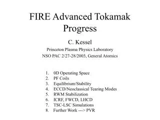
FIRE’s Efforts to Self-Consistently Simulate Advanced Tokamak Modes • 0-D Systems Analysis: • Determine viable operating point global parameters that satisfy constraints • Plasma Equilibrium and Ideal MHD Stability: • Determine self-consistent stable plasma configurations to serve as targets • Heating/Current Drive: • Determine current drive efficiencies and deposition profiles • Transport:(GLF23 and pellet fueling models to be used in TSC) • Determine plasma density and temperature profiles consistent with heating/fueling and plasma confinement • Dynamic Evolution Simulations: • Demonstrate self-consistent startup/formation and control including transport, current drive, and equilibrium • Edge/SOL/Divertor: • Find self-consistent solutions connecting the core plasma with the divertor
0D Analysis Includes • Power balance: energy confinement time scaling • Fusion cross-section from Bosch-Hale formulation • Particle balance: self-consistent helium content (input He*/E), quasi-neutrality, input impurity fractions • Radiation: bremsstrahlung, cyclotron (new Albajar formulation), line (coronal equilibrium) • Current diffusion time, flux consumption (Hirshman-Nielson) with neoclassical resistivity • Bootstrap current (equilibrium fits) and external CD: input CD efficiency • Fast alpha beta contribution • Parabolic or parabolic+pedestal profiles • Post-processor used for database screening
0D Power/Particle Balance Identifies Operating Space for FIRE AT • Heating/CD Powers • ICRF/FW, 30 MW • LHCD, 30 MW • Using CD efficiencies • (FW)=0.20 A/W-m2 • (LH)=0.16 A/W-m2 • P(FW) and P(LH) determined at r/a=0 and r/a=0.75 • I(FW)=0.2 MA • I(LH)=Ip(1-fbs) • Scanning Bt, q95, n(0)/<n>, T(0)/<T>, n/nGr, N, fBe, fAr • Q=5 • Constraints: • (flattop)/(CR) determined by VV nuclear heat (4875 MW-s) or TF coil (20s at 10T, 50s at 6.5T) • P(LH) and P(FW) ≤ max installed powers • P(LH)+P(FW) ≤ Paux • Q(first wall) < 1.0 MW/m2 with peaking of 2.0 • P(SOL)-Pdiv(rad) < 28 MW • Qdiv(rad) < 8 MW/m2 Generate large database and then screen for viable points
FIRE’s Q=5 AT Operating Space Access to higher tflat/j decreases at higher N, higher Bt, and higher Q, since tflat is set by VV nuclear heating Access to higher radiated power fractions in the divertor enlarges operating space significantly
Observations from 0D Analysis for Burning Plasma AT • In order to provide reasonable fusion gain Q≥5, can’t operate at low density to maximize CD efficiency • Density profile peaking is beneficial (pellets or ITB), since broad densities increase required H98 and PCD • Access to high density relative to Greenwald density, in combination with high bootstrap current fraction gives the lowest required H98 • H98 ≥1.4 are required to access flattop/curr diff > 3, however, the ELMy H-mode scaling law is known to have a degradation that is not observed on individual experiments • Radiative core/divertor solutions are a critical area for the viability of burning AT experiments due to high P+PCD, suggesting impurity control techniques
FIRE’s AT Operating Space Q = 5-10 accessible N = 2.5-4.5 accessible fbs = 50-90+ accessible tflat/tj = 1-5 accessible If we can access….. H98(y,2) = 1.2-2.0 Pdiv(rad) = 0.5-1.0 P(SOL) Zeff = 1.5-2.3 n/nGr = 0.6-1.0 n(0)/<n> = 1.5-2.0
Examples of Q=5 AT Points That Obtain flat/J > 3 HH < 1.75, satisfy all power constraints, Pdiv(rad) < 0.5 P(SOL)
Dynamic Simulations of FIRE AT Discharges with TSC-LSC • Free-boundary time-dependent simulation 2D MHD equations, Maxwell’s equations, and 1D transport equations for particles, energy, and current, coupled thru boundary conditions to the PF coils • Physics models • Transport coefficients • Heating/fueling deposition for alphas, NBI, ICRF, etc. • Current drive and bootstrap current • Sawteeth • Radiation • Impurity transport • Feedback control systems • High-n ballooning • LSC is a lower hybrid ray-tracing code
Vertical position control coils Passive stabilizers TSC Model
TSC-LSC Simulation ofQ≈5FIRE AT Discharge Ip = 4.5 MA, Bt = 6.5 T, N = 4.1, H98=1.7, n/nGr= 0.85, n(0)/n = 1.45 = 4.7%, p = 2.35, flattop/curr diff = 3.5, Zeff = 2.2, q(0) = 4.0, qmin = 2.7, q95 = 4.0
TSC-LSC Simulation of Q=5 AT Burning Plasma During flattop, t=10-41s li(3)=0.42
MHD in FIRE AT Plasmas and its Control • n=∞ ballooning modes ---> limit pressure locally, not observed experimentally since very localized, self-limiting by adjusting profile to be marginally stable • n=0 vertical instability ---> slowed with conducting structures and controlled with coils that provide a radial magnetic field • n=1 external kink modes (resistive wall modes) ---> disruptive, slowed with conducting structures and can be controlled with plasma rotation and/or direct feedback with saddle coils, strong influence of error fields • 1 < n < 4 external kink modes ---> disruptive??, behavior similar to n=1, however, more localized toward the plasma boundary, and may set lower -limit than n=1, should be controllable like n=1 if necessary • 4 < n < 20 peeling modes ---> ballooning and kink mode character, localized to the plasma edge, associated with pressure pedestal and associated bootstrap current, and considered primary candidate for ELMs, plasma shaping has significant influence • Neo-classical tearing modes ---> non-disruptive but reduce achievable in long pulse discharges, controllable with current driven at island or by modifying current profile to increase |’|
Updating FIRE AT Equilibrium Targets Based on TSC-LSC Equilibrium TSC-LSC equilibrium Ip=4.5 MA Bt=6.5 T q(0)=3.5, qmin=2.8 N=4.2, =4.9%, p=2.3 li(1)=0.55, li(3)=0.42 p(0)/p=2.45 n(0)/n=1.4 Stable n= Stable n=1,2,3 with no wall √V/Vo
Stabilization of n=1 RWM is a High Priority on FIRE Feedback stabilization analysis with VALEN shows strong improvement in , taking advantage of DIII-D experience, most recent analysis indicates N(n=1) can reach 4.2 What is impact of n=2??
Stabilization of n=1 RWM on DIII-D Experiments on DIII-D have verified plasma rotation stabilization by reducing the error fields (amplified by RWM’s) that slow the plasma down, and VALEN analysis shows that better sensors and in-vessel feedback coils strongly improve N
Theoretical Results for n=1 RWM Stabilization from MARS and VALEN VALEN shows that feedback can work with detailed structure and coil model MARS shows that feedback can work with simple structure and coil model HBT-EB
How Do n=2-4 Manifest Themselves if They Are Linearly Ideal Unstable Shape study on DIII-D AT plasmas n=2 and n=3 would not allow access to the n=1 -limit These modes appear too broad to be peeling modes This feature is common from wall stabilized ideal MHD analysis Are these modes triggering tearing modes that subsequently become NTM’s?? ---> DIII-D wall at 1.5a
Neo-Classical Tearing Modes for FIRE AT Modes Target Bt=6.5-7 T for NTM control, to utilize 170 GHz from ITER R&D Must remain on LFS for resonance and use O-mode, due to high Bt ECCD efficiency?? (trapping) Can we avoid NTM’s with j() and q>2.0 or do we need to suppress them?? Ro Ro+a Bt=6.5 T fce=182 fce=142 170 GHz Ro Ro+a Bt=7.5 T fce=210 fce=164 200 GHz Ro Ro+a Bt=8.5 T fce=238 fce=190 Can we rely on OKCD to suppress NTM’s far off-axis on LFS versus ECCD ?? (enhanced Ohkawa affect at plasma edge)
J. Decker, APS 2002,MIT OKCD allows LFS EC deposition, with similar A/W as ECCD on HFS
Comments on ECCD in FIRE • ASDEX-U shows that 3/2 island is suppressed for about 1 MW of power with IECCD/Ip = 1.6%, giving 0.013 A/W • Ip=0.8 MA and N=2.5 • DIII-D shows that 3/2 island is suppressed for about 1.2-1.8 MW with jEC/jBS = 1.2-2.0 • Ip=1.0-1.2 MA, N=2.0-2.5 • OKCD analysis of Alcator-CMOD gives about 0.0056 A/W • FIRE’s current requirement should be about 15 times higher than ASDEX-U (scaled by Ip and N2) • Need about 200 kA, which would require about 35 MW?? Early detection reduces power alot according to ITER • Do we need less current for 5/2 or 3/1, do we need to suppress them?? • Is 170 GHz really the cliff in EC technology?? MIT, short pulse results
FIRE EC Geometry ce = n(0)=4.51020 f pe=9√n Rays are bent as they approaches pe EC launcher Rays must be launched with toroidal directionality for CD pe > cutofffor 170 GHz
Neo-Classical Tearing Mode Stabilization on DIII-D, ASDEX-U and JT-60U • Actively stabilize NTM’s ---> must spatially track island • ECCD • LHCD (Compass-D) • Passively avoid NTM’s • q > 2? • J() that is stable? DIII-D Required IECCD scales as Ip and N2 ASDEX-U
Heating and Current Drive for FIRE AT Plasmas and its Control • ICRF ion heating on and off-axis • ICRF/FW for electron heating and on-axis CD • LH for off-axis CD and electron heating • EC for NTM control off-axis deposition (no analysis yet) • NBI?? presently being examined (no AT analysis yet) • High energy needed for ELMy H-mode, not practical • AT’s have slightly lower density, more density peaking, and off-axis deposition is desirable ---> prefer conventional energies 120 keV • Heating and Current Drive directly affect Transport
ICRF Ion Heating 80-120 MHz, 2 strap antennas, 4 ports, 20 MW (10 MW upgrade) He3 minority, 2T, 2D, H minority accessible resonances at center and off-axis (C-Mod ITB) ----> full wave analysis gives 75% power on ions
ICRF/FW Viable for FIRE On-Axis CD Calculations assume same ICRF ion heating system frequency range, approximately 40% of power absorbed on ions, can provide required AT on-axis current of 0.3-0.4 MA with 20 MW (2 strap antennas) PICES (ORNL) and CURRAY(UCSD) analysis f = 110-115 MHz n|| = 2.0 n(0) = 5x10^20 /m3 T(0) = 14 keV 40% power in good part of spectrum (2 strap) ----> 0.02-0.03 A/W CD efficiency with 4 strap antennas is 50% higher Operating at lower frequency to avoid ion resonances, vph/vth?? E. Jaeger, ORNL
Benchmarks for LHCD Between LSC and ACCOME (Bonoli) Trapped electron effects reduce CD efficiency Reverse power/current reduces forward CD Less than 1.0 MW is absorbed by alphas Recent modeling with CQL and ACCOME/LH19 will improve CD efficiency, but right now…….. Bt=8.5T ----> 0.25 A/W-m2 Bt=6.5T ----> 0.16 A/W-m2 FIRE has increased the LH power from 20 to 30 MW f=4.6 GHz n ||=2.0 n||=0.3
Energy and Particle Transport in FIRE AT Plasmas and Its Control • Significant reductions in particle and energy transport have been achieved at the plasma edge (ETB) and in the core (ITB) • Most present tokamaks have NBI, which provides sheared rotation and strongly stabilizes micro-instabilities • Negative magnetic shearand Shafranov shift are also found to stabilize microinstabilites • Heating, current drive, rotation, pellets, and impurities are found to influence transport • It appears that transport barriers can be made to “leak a little” to avoid excessive particle buildup • Lots of other observations ---> C-Mod ITB’s with off-axis ICRF, JET ITB’s triggered by qmin passing rational surfaces,… • The control of transport (pressure profile control) is critical to achieving high bootstrap current fractions, that remain MHD stable • The transport barrier may be an ideal method for controlling the pressure profile ---> by turning the ITB on and off, with a given frequency, a desirable pressure profile could be produced
Transport Has Multiple Scales and Multiple Stabilization Mechanisms
GLF23 AT Predictive Modeling Is Improving Kinsey Ti, Te V GLF23, ver. 1.61 model DIII-D expt
HFS Launch V=125 m/s, set by ORNL pellet tube geometry Vertical and LFS launch access higher velocities
HFS Pellet Launch and Density Peaking ---> Needs Strong Pumping Simulation by W. Houlberg, ORNL, WHIST FIRE reference discharge with uniform pellet deposition, achieves n(0)/<n> ≈ 1.25 P. T. Lang, J. Nuc. Mater., 2001, on ASDEX and JET L. R. Baylor, Phys. Plasmas, 2000, on DIII-D
FIRE’s Divertor Must Handle Attached(25 MW/m2) and Detached(5 MW/m2) Operation D. Dreimeyer, M. Ulrickson
Other Issues for FIRE AT Plasmas • Alpha particle losses from ripple, aggravated by high safety factor and low Ip and Bt • TAE’s are also driven more easily at high safety factor (not analized) • PF Coil operational flexibility for AT modes in FIRE
TF Ripple and Alpha Particle Losses TF ripple very low in FIRE (max) = 0.3% (outboard midplane) Alpha particle collisionless + collisional losses = 0.3% for reference ELMy H-mode For AT plasmas alpha losses range from 2-8% depending on Ip and Bt ----> are Fe inserts required for AT operation??? Optimize for Bt=6.5T
Fe Shims for Ripple Reduction for AT Modes in FIRE TF Coil Fe Shims Outer VV Inner VV
PF Coil Capability for AT Modes AT modes have flattops ranging from 16-50 s • Advanced tokamak plasmas • Range of current profiles: 0.35 < li(3) < 0.55 • Range of pressures: 2.50 < N < 5.0 • Range of flattop flux states: chosen to minimize heating and depends on flattop time (determined by Pfusion) • Ip limited to ≤ 5.5 MA • Lower li operating space led to redesign of divertor coils • PF1 and PF2 changed to 3 coils and total cross-section enlarged • Presently examining magnet stresses and heating for AT scenarios
AT Physics Capability on FIRE Control Strong plasma shaping and control Pellet injection, divertor pumping, impurity injection FWCD (electron heating/CD) on-axis, ICRF ion heating on/off-axis LHCD (electron heating/CD) off-axis ECCD (LFS, electron heating) off-axis, MHD control RWM MHD feedback control NBI ?? (need to examine for AT parameters!!) t(flattop)/t(curr diff) = 1-5 Diagnostics MHD J Profile P-profile Rotation
Ongoing Work to Establish Advanced Tokamak Regime for FIRE • Establish PF Coil operating limits • Revisit Equilibrium/Stability Analysis • Use recent GLF23 update in AT scenarios • LHCD efficiency updates • EC with FIRE’s parameters • Orbit calculations of lost alphas for scenario plasmas, Fe shim requirements • RWM coil design in port plugs and RF ports • Determine possible impact of n=2 RWM on access to high N • Examine NBI for FIRE AT parameters