Download
1 / 6
70 likes | 187 Views
ENS 203- Amplitude Modulation and Demodulation Lab 6 Radio Experiment Meric Ozcan. After you configure the radio as specified in your lab sheet, you will test your radio’s operation with a test signal from the

E N D
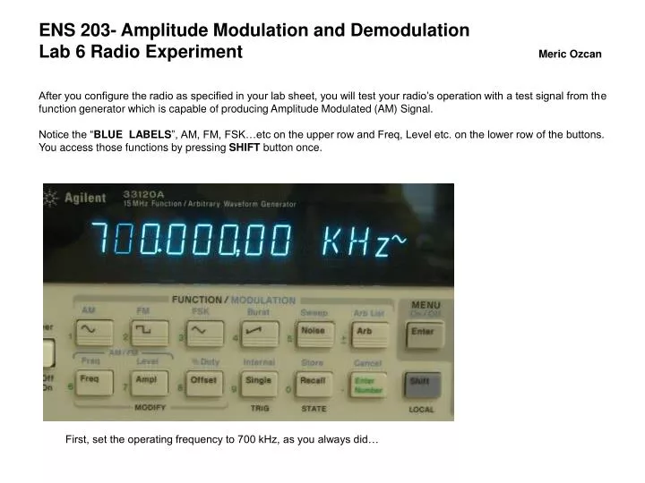
ENS 203- Amplitude Modulation and Demodulation Lab 6 Radio Experiment Meric Ozcan After you configure the radio as specified in your lab sheet, you will test your radio’s operation with a test signal from the function generator which is capable of producing Amplitude Modulated (AM) Signal. Notice the “BLUE LABELS”, AM, FM, FSK…etc on the upper row and Freq, Level etc. on the lower row of the buttons. You access those functions by pressing SHIFT button once. First, set the operating frequency to 700 kHz, as you always did…
Next set the Amplitude to 100 mV peak to peak… At this point we have a carrier at 700 kHz. Now we have to apply modulation to the carrier. Function Generator Setup
In order to apply modulation to the carrier We have to specify three things: 1- Modulation type (in this case AM modulation) 2- Modulation Frequency 3- Modulation Depth You first press SHIFT then AM At this point signal is AM modulated, the picture below shows already that it is 1.0 kHz modulating signal. If it shows some other frequency, just set it to 1 kHz by pressing SHIFT and FREQ and adjust it with the knob… At this point we completed the first two steps… Modulation
Modulation and Final Setup Last item in the modulation setup is the modulation depth. Press SHIFT and the LEVEL and set the depth 30-50 % range by the knob. Picture below shows the 30 % depth. Now connect the signal generator output to the antenna input of your radio. If everything works you should hear 1 kHz tone from the speaker! Next, connect one channel of the oscilloscope to the antenna input of the radio (same point as the signal generator). Connect the second channel to the detector output. The actual signals you should see are on the next page.
Top signal is the 700 kHz carrier signal modulated with 1 kHz signal (30% modulation depth) You see the 700 kHz amplitude modulated signal as a continuous band since there are just too many oscillations for the time base setting we have here (think about it). Bottom signal is the output of the diode, as you see it is just the 1 kHz signal (with a negative DC, why?) Signal Input and Demodulated Signal At this point you should hear the 1 kHz tone from the speaker. If that is the case just remove the signal generator and connect the antenna. Your radio is working… Once you connect the antenna you should be hearing the TRT Istanbul broadcast.
Low Frequency Carrier Example I just put this example to show the modulation clearly. In this case the carrier is 10 kHz and the modulation is 1 kHz. As you see, the amplitude of 10 kHz signal is modulated with 1 kHz signal…