Download
1 / 73
1.42k likes | 2.72k Views
Chapter 1: Data Storage. Chapter 1: Data Storage. 1.1 Bits and Their Storage Logic 1.2 Main Memory 1.3 Mass Storage 1.4 Representing Information as Bit Patterns 1.5 The Binary System. Chapter 1: Data Storage (continued) . 1.6 Storing Integers 1.7 Storing Fractions

E N D
Chapter 1: Data Storage 1.1 Bits and Their Storage Logic 1.2 Main Memory 1.3 Mass Storage 1.4 Representing Information as Bit Patterns 1.5 The Binary System
Chapter 1: Data Storage (continued) 1.6 Storing Integers 1.7 Storing Fractions 1.8 Data Compression* 1.9 Communications Errors *not covered
Bits and Bit Patterns Bit: Binary Digit (0 or 1) Bit Patterns are used to represent information. Numbers Text characters Images Sound And others
Hardware Advances representing information as electrical signals led to telegraph in mid-1800s needed device to control current flow telegraph clicker, relays, vacuum tubes transistor in 1948 collector, emitter, base photography – end of 18th century based on principle that some chemicals change their properties when exposed to light silver nitrate changes to metallic silver
Switches normally open switch in out control in out 0 1 0 0 0 control 1 0 1
Switches Normally closed switch in out control in out 0 1 0 0 1 control 1 0 0
Boolean Operations Boolean Operation: An operation that manipulates one or more true/false values Specific operations AND OR XOR (exclusive or) NOT
Figure 1.1 The Boolean operations AND, OR, and XOR (exclusive or)
Boolean operations AND NOT P * Q Q P ' 0 1 0 0 0 0 1 P P 0 1 1 0 1
Gates Gate: A device that computes a Boolean operation Often implemented as (small) electronic circuits Provide the building blocks from which computers are constructed VLSI (Very Large Scale Integration)
Figure 1.2 A pictorial representation of AND, OR, XOR, and NOT gates as well as their input and output values
How to construct a logical expressionfrom a logic table Look at each line in the table for which the result is TRUE (1) For each of those rows Find the P and Q values Build an AND statement with the variable itself, if it is TRUE with the negation of the variable, if it is FALSE Connect the statements created above with ORs
1-bit comparator P * Q P' P (P*Q) + (P' * Q') Q P' * Q' Q' (P * Q) + (P' * Q')
Using Circuits to do Arithmetic Interpret current (true) as a 1 and no current (false) as a 0, we can do math b + 0 1 0 00 01 a 1 01 10
Arithmetic Note – the sum digit is 1 only when both inputs are different The carry digit is 1 only when both inputs are 1 so carry bit is simply carry = a * b build a logic table for the sum
Addition – Full Adder Half adder adds two numbers giving sum and carry result, but no provision for a carry in. So we hook two half adders together to create a 1-bit full-adder
Adding two 4-bit numbers Let's add 0101 and 0110 1 0 0 0 1 1 0 1 = 0 FA FA FA FA overflow 0 0 1 0 1 0 1 1
Flip-flops Flip-flop: A circuit built from gates that can store one bit. One input line is used to set its stored value to 1 One input line is used to set its stored value to 0 While both input lines are 0, the most recently stored value is preserved
Figure 1.4 Setting the output of a flip-flop to 1 (continued)
Main Memory Cells Cell: A unit of main memory (typically 8 bits which is one byte) Most significant bit: the bit at the left (high-order) end of the conceptual row of bits in a memory cell Least significant bit: the bit at the right (low-order) end of the conceptual row of bits in a memory cell
Main Memory Addresses Address: A “name” that uniquely identifies one cell in the computer’s main memory The names are actually numbers. These numbers are assigned consecutively starting at zero. Numbering the cells in this manner associates an order with the memory cells.
Memory Terminology Random Access Memory (RAM): Memory in which individual cells can be easily accessed in any order Dynamic Memory (DRAM): RAM composed of volatile memory
Measuring Memory Capacity Kilobyte: 210 bytes = 1024 bytes Example: 3 KB = 3 times1024 bytes Sometimes “kibi” rather than “kilo” Megabyte: 220 bytes = 1,048,576 bytes Example: 3 MB = 3 times 1,048,576 bytes Sometimes “megi” rather than “mega” Gigabyte: 230 bytes = 1,073,741,824 bytes Example: 3 GB = 3 times 1,073,741,824 bytes Sometimes “gigi” rather than “giga” Terabyte: 240 bytes Petabyte: 250 bytes Exabyte: 260 bytes
Mass Storage On-line versus off-line Typically larger than main memory Typically less volatile than main memory Typically slower than main memory
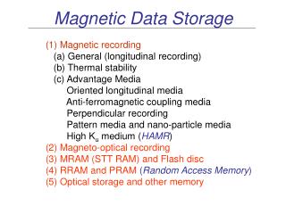
Mass Storage Systems Magnetic Systems Disk Tape Optical Systems CD DVD Flash Drives
CDs and DVDs reflective material covered with clear protective coating. information is recorded by creating variations in this reflective surface high powered laser beams to created pits low powered laser beam to retrieve data smooth unpitted area is a 1, pitted area is interpreted as a 0
Flash Drives magnetic & optical devices require physical motion to store and retrieve data slow in flash memory, bits are stored by sending electronic signals directly to the storage medium where they cause electrons to be trapped in tiny chambers of silicon dioxide, thus altering the characteristics of small electronic circuits good for off-line storage, digital cameras, phones, PDAs
Files File: A unit of data stored in mass storage system Fields and keyfields Physical record versus Logical record Buffer: A memory area used for the temporary storage of data (usually as a step in transferring the data)
Representing Text Each character (letter, punctuation, etc.) is assigned a unique bit pattern. ASCII: Uses patterns of 7-bits to represent most symbols used in written English text modern – uses 8-bit code where last 128 characters are dependent on manufacturer Unicode: Uses patterns of 16-bits to represent the major symbols used in languages world wide ISO standard: Uses patterns of 32-bits to represent most symbols used in languages world wide – billions of characters
Representing Numeric Values Binary notation: Uses bits to represent a number in base two Limitations of computer representations of numeric values Overflow – occurs when a value is too big to be represented Truncation – occurs when a value cannot be represented accurately
The Binary System The traditional decimal system is based on powers of ten. The Binary system is based on powers of two.
Figure 1.17 An algorithm for finding the binary representation of a positive integer
Figure 1.18 Applying the algorithm in Figure 1.15 to obtain the binary representation of thirteen
Hexadecimal Notation Hexadecimal notation: A shorthand notation for long bit patterns Divides a pattern into groups of four bits each Represents each group by a single symbol Example: 10100011 becomes A3