Download

1 / 66
730 likes | 1.21k Views
17. 12-Lead ECGs and Electrical Axis. Fast & Easy ECGs, 2nd E – A Self-Paced Learning Program. Heart’s Electrical Activity. Depolarization and repolarization of the atria and ventricles are electrical events

E N D
17 12-Lead ECGs and Electrical Axis Fast & Easy ECGs, 2nd E – A Self-Paced Learning Program
Heart’s Electrical Activity • Depolarization and repolarization of the atria and ventricles are electrical events • The ECG detects this electrical activity and displays it on the oscilloscope or prints it
Planes of the Heart • With the 12-lead ECG, electrodes are placed at specific spots on the patient’s extremities and/or torso and chest wall to view the heart’s electrical activity from two distinct planes: • frontal • horizontal • These planes provide a cross-sectional view of the heart
Frontal Plane • Leads I, II, III and aVR, aVL, and aVFview the heart along this plane • Referred to as limb leads • Four electrodes are positioned either on the extremities or on the torso • Can be placed far down on limbs or close to hips and shoulders, but they must be even (right vs. left)
Limb Leads - Standard • Leads I, II, and III form what is known as Einthoven’s triangle, which is an electrically equilateral triangle based on these three limb leads’ positions relative to one another • leads intersect at angles of 60 degrees I
Limb Leads - Lead I • Positive electrode - left arm (or left side of chest below the clavicle in the midclavicular line) • Negative electrode - right arm (or right side of chest below the clavicle in the midclavicular line) • Ground electrodes • left leg (or left side of chest in midclavicular line just beneath last rib) • Right leg (or right side of chest in midclavicular line just beneath last rib • Waveforms are positive
Limb Leads - Lead II • Positive electrode - left leg (or on left side of chest in midclavicular line just beneath last rib) • Negative electrode - right arm (or right side of chest below the right clavicle in the midclavicular line) • Ground electrode • Left arm (or left side of chest in midclavicular line just below the left clavicle) • Right leg (or right side of chest in midclavicular line just beneath last rib) • Waveforms are positive
Limb Leads - Lead III • Positive electrode - left leg (or left side of the chest in midclavicular line just beneath last rib) • Negative electrode - left arm (or left side of chest below the clavicle in the midclavicular line) • Ground electrode • Right arm (or right side of chest in midclavicular line just below the clavicle) • Right leg (or right side of chest in midclavicular line just beneath last rib) • Waveforms are positive or biphasic
Limb Leads - Augmented Leads • Includes aVR, aVL and aVF • Are unipolar • Enhanced by ECG machine because waveforms produced by these leads are normally small I
Limb Leads - Lead aVR • Positive electrode placed on the right arm (or right side of chest below the clavicle in the midclavicular line) • Waveforms have negative deflection
Limb Leads - Lead aVL • Positive electrode placed on left arm (or left side of chest below the clavicle in the midclavicular line) • Waveforms have positive deflection
Limb Leads - Lead aVF • Positive electrode located on left leg (or left side of chest below the last rib in the midclavicular line) • Waveforms have a positive deflection
Precordial Leads • Includes leads V1, V2, V3, V4, V5 and V6 • Positioned in order across the chest • Unipolar • Opposing pole is center of heart as calculated by ECG I
Lead V1 • Electrode positioned in fourth intercostal space just to the right of the sternum • Faces and is close to the right ventricle • Also has a view of ventricular septum
Lead V1 • Steps for positioning the V1 electrode
Lead V2 • Positioned in 4th intercostal space just to the left of the sternum • Horizontally, it is at the same level as lead V1 but on the opposite side the sternum • Just like lead V1, V2 faces and is close to the right ventricle • Although it has a view of the right ventricle and anterior wall of the heart, it is more recognized for its view of the ventricular septum
Lead V2 • Steps for positioning the V2 electrode
Lead V3 • Located midway between leads V2 and V4 • Views anterior wall of the left ventricle • Depolarization of the left ventricle moves perpendicular to the positive electrode, resulting in a biphasic waveform I
Lead V4 • Is placed at the 5th intercostal space n the midclavicular line • Views the anterior wall of left ventricleand is close to the heart’s apex • Depolarization of the left ventricle moves perpendicular to the positive electrode resulting in a biphasic waveform I
Lead V4 • Steps for positioning the V4 electrode
Lead V5 • Placed in 5th intercostal space at the anterior axillary line • Horizontally, it is even with V4 but in the anterior axillary line • Views lateral wall of the left ventricle • Depolarization of left ventricle moves toward the positive electrode, producing a tall R wave I
Lead V5 • Steps for positioning the V5 electrode
Lead V6 • Located horizontally level with V4 and V5 at the midaxillary line • Views lateral wall of left ventricle • Depolarization of left ventricle moves toward the positive electrode producing a tall R wave I
Lead V6 • Steps for positioning the V6 electrode
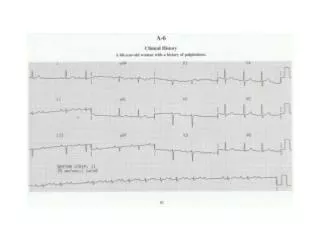
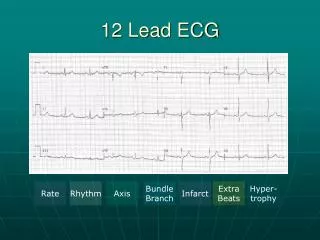
12 Lead ECG Waveforms • Each view provides different information • When assessing the 12 lead ECG look for characteristic normalcy and changes in all leads
Contiguous Leads • Two leads that look at neighboring anatomical areas of the heart are said to be contiguous
Right Ventricular Leads • View the right ventricle • Are in addition to the 12 lead ECG and require relocating the precordial ECG electrodes
Posterior Leads • View the posterior surface of the heart • Are in addition to the 12 lead ECG and require relocating the precordial electrodes
Electrical Axis • The 12-lead ECG can measure the axis of the electrical flow of energy during the cardiac cycle
Instantaneous Vectors • Cardiac cell depolarization and repolarization produces many small electrical currents • Sum of these currents called instantaneous vectors • Average of instantaneous vectors called the mean vector I
Mean Electrical Axis • Direction of the mean vector called the mean electrical axis • Axis is defined in the frontal plane only
ECG Deflection • Wave of depolarization and its affect on the ECG
QRS Axis • Most important and frequently determined axis
Ventricular Depolarization and Mean QRS Axis • Interventricular septum depolarization represents the first cardiac vector associated with ventricular depolarization • A sequence of vectors is produced as the Purkinje fibers carry the impulse from the endocardial lining of the RV and LV through the ventricular wall toward the epicardium
Ventricular Depolarization and Mean QRS Axis • Completion of right ventricular activation occurs first • The thinner wall of the RV transmits impulse quicker than the thicker wall of LV
Mean QRS Axis • The small depolarization vectors of the thicker LV are larger • Therefore, the mean QRS axis points more to the left I
Position of Mean QRS Axis • Limb leads provide information about the frontal plane and are used to determine the position of the mean QRS axis • Described in degrees within an imaginary circle drawn over the patient’s chest I
Position of Mean QRS Axis • AV node is center of circle • Intersection of all lines divides circle into equal, 30-degree segments • Lead I starts at +0 degrees and is located at the three o’clock position • Lead aVF starts at +90 degrees and is located at the six o’clock position
Position of Mean QRS Axis • Mean QRS axis normally points downward and to patient’s left (between 0 and +90 degrees)
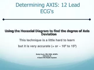
Determining Electrical Axis • Use leads I and aVF • These two leads can best detect variations in the heart’s electrical axis I
Determining Electrical Axis • If the mean QRS vector directed anywhere between -90º and +90º, positive QRS complex in lead I I
Determining Electrical Axis • If mean QRS vector directed between 0º and +180º, positive QRS complex in lead aVF I
Right Axis Deviation • An axis between +90 and±180 degrees indicates right axis deviation
Left Axis Deviation • An axis between 0 and −90 degrees indicates left axis deviation
Determining Electrical Axis • The deflection of the QRS complexes in leads I and aVF help identify electrical axis I
Determining Electrical Axis • Location of axis influenced by: • Heart’s position in the chest • Heart size • Patient’s body size • Conduction pathways • Force of electrical impulses being generated
Practice Makes Perfect • Determine if the mean QRS is normal or if there is axis deviation I