Download
1 / 44
440 likes | 599 Views
MICE Cooling Channel Magnets: • Spectrometer Solenoid Procurement • RF Module Coupling Coil Proposal. Steve Virostek Lawrence Berkeley National Lab. NFMCC 07 @ UCLA January 31, 2007. MICE Cooling Channel Layout. AFC Module 2. RFCC Module 1. Spectrometer Solenoid 1. Spectrometer

E N D
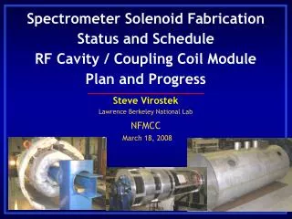
MICE Cooling Channel Magnets:• Spectrometer Solenoid Procurement• RF Module Coupling Coil Proposal Steve Virostek Lawrence Berkeley National Lab NFMCC 07 @ UCLA January 31, 2007
MICE Cooling Channel Layout AFC Module 2 RFCC Module 1 Spectrometer Solenoid 1 Spectrometer Solenoid 2 AFC Module 3 RFCC Module 2 AFC Module 1 Steve Virostek - Lawrence Berkeley National Laboratory
Spectrometer Solenoid Overview • Order for two spectrometer solenoid magnets was placed with Wang NMR by LBNL in June ‘06 • Design review was held by Wang on Sept 6, 2006 • Complete design package book provided to LBNL • Detailed magnet design is now complete • Superconducting wire was provided by LBNL (IIT) • First machined coil former completed last week • Coil winding will begin within two weeks • First magnet scheduled to be shipped end Aug 07 Steve Virostek - Lawrence Berkeley National Laboratory
The spectrometer solenoids provide a uniform field for the scintillating fiber tracker & match the uniform field section into the rest of MICE The long center coil with its two short end coils are designed to generate a 4 T field Field uniformity is better than 0.3% over a 1000 mm long, 300 mm diameter region Uniformity is better than 0.1% over most of the region Purpose of the Spectrometer Solenoids Steve Virostek - Lawrence Berkeley National Laboratory
MICE Field on Axis in the Flip Mode Spectrometer Solenoid on Axis Field Steve Virostek - Lawrence Berkeley National Laboratory
Spectrometer Solenoid Cold Mass End Coil 2 Coil Cover End Coil 1 690 mm Match Coil 1 2544 mm 490 mm Center Coil Liquid Helium Space Match Coil 2 Coil Spacer Steve Virostek - Lawrence Berkeley National Laboratory
First Completed Coil Winding Form Steve Virostek - Lawrence Berkeley National Laboratory
Spectrometer Solenoid Conductor 1.65 mm 1.00 mm Cu/SC = 3.9 ± 0.4 Twist pitch: 19±3 mm 121.5 km purchased 41 mm Nb-Ti 222 Filaments RRR > 70 @ 4.2 K Steve Virostek - Lawrence Berkeley National Laboratory
Design Overview (coil construction) • Single piece 6061-T6 aluminum coil former • Each layer wet wound using Stycast 2850 FT • 2.5 mil thick fiberglass between winding layers • Aluminum coil banding will provide hoop force support and ensure coils are tight after cooldown • Conductor joints are to be lapped by at least 24” to minimize the I2R losses • Passive quench protection will be provided by a system of diodes & resistors Steve Virostek - Lawrence Berkeley National Laboratory
Cold Mass Support System (50 T axial force) 300 K Support End Cold Mass Assembly 60 K Support Intercept Support Band 4 K Support End Steve Virostek - Lawrence Berkeley National Laboratory
4.2 K Coolers Lead Neck He Gas Pipe Condenser Tank Cold Mass Cold Mass Support Liquid Pipe 4K End 60K Intercept 300K End Steve Virostek - Lawrence Berkeley National Laboratory
Design Overview (coil cooling) • Indirect cooling using liquid helium condensers • Baseline design will use two cryocoolers but will allow mounting of a third cooler, if necessary • High TC leads will be accessible by means of a removable cover plate • 60K (or less) thermal shield is conductively cooled using the first stage of the cryocoolers • Thermal shield copper mass will protect the high TC leads and provide extra cooling margin Steve Virostek - Lawrence Berkeley National Laboratory
Lead Neck Cooler Neck He Filler Neck Cold Mass Support PMT Iron Shield Space for Radiation Shield Support Stand Steve Virostek - Lawrence Berkeley National Laboratory
Design Overview (PV’s & supports) • Helium vessel (Al) and vacuum vessel (304SS) to be designed & tested according to PV code • He vessel will contain two relief paths for safety • Unidirectional S-2 fiberglass cold mass supports using race-track shaped links (safety factor of 4) • 304 SS support design derived from LBNL/Oxford • Cold mass support design allows cold shipping Steve Virostek - Lawrence Berkeley National Laboratory
~330 mm 1000 mm MICE Scintillating Fiber Tracker Module DB/B = ±0.105% at R=0, L=1050 mm DB/B = ±0.262% at R=150 mm, L=1050 mm The Blue rings are the tracker scintillating fiber planes. Plane spacing: 150mm, 180mm, 200mm and 470mm. All fiber planes are in the magnet good field region. Steve Virostek - Lawrence Berkeley National Laboratory
Estimated Heat Loads • The magnets can be cooled with a pair of 1.5 W pulse tube coolers • The temperature of the cooler first stage is about 52 K instead of 60 K • Given the temperature margin, the magnets can operate at 4.5 K • The peak field at the cooler rotary slide valve is about 0.05 T Steve Virostek - Lawrence Berkeley National Laboratory
Magnet Coil Load Lines Margin @ 4.2 K: M1 = ~1.7 K M2 = ~ 1.9 K E1 = ~ 1.6 K C = ~ 2.0 K E2 = ~1.5 K Steve Virostek - Lawrence Berkeley National Laboratory
Quench Protection & Power Supply Hookup Steve Virostek - Lawrence Berkeley National Laboratory
Pulse Tube Cryocoolers • Magnets to be cooled to as low as 45 K (1st stage) and 3.8 K (2nd stage) using two 1.5 W pulse tube coolers • Magnetic field at the cooler rotary valve motors is ~0.05 T (no iron shielding needed on the valve motors) • Cryocoolers (up to three) can be installed and removed without breaking cryostat vacuum • Coolers connected to He liquid bath w/a thermal siphon heat pipe to reduce DT between coil & cooler 2nd stage • Four Cryomech 1.5 W pulse tube coolers ordered by IIT – first unit shipping to Wang on February 19th Steve Virostek - Lawrence Berkeley National Laboratory
Magnet Power Supplies • Three power supplies of +300 A at ±10 V for the center and two match coils (shared for 2 magnets) • two quadrant power supply • current regulation of < ±0.01% from 50 A to 275 A • Four power supplies of ±50 A at ±5 V for the two end coils (2 per magnet) • four quadrant power supply • current regulation of < ±0.03% from 5 A to 45 A • Power supply specification is complete • Lead time is 3 months – order to be placed soon Steve Virostek - Lawrence Berkeley National Laboratory
Schedule Summary Steve Virostek - Lawrence Berkeley National Laboratory
Summary • Detailed magnet design is now complete • 1st coil former arriving at Wang this week • High TC leads will arrive early February • Cryomech cryocoolers (4 each) on order • Power supply spec is complete – order soon • First magnet to be shipped by end Aug 07 • Second magnet to follow 1 month later Steve Virostek - Lawrence Berkeley National Laboratory
MICE Coupling Coil Fabrication Plan Proposal Lawrence Berkeley National Laboratory (LBNL) Institute of Cryogenic & Superconductivity Technology (ICST) at the Harbin Institute of Technology
Progress towards LBNL/ICST Collaboration • Scope: design, fabricate and test one MuCool coil and two MICE coupling coils • Preliminary discussions began last year • Mike Green visit to ICST 4/06 and at MICE CM15 & CM16 • LBNL visit to ICST at Harbin in December ‘06 • Attendees: M. Zisman, D. Li, S. Virostek, M. Green • ICST presented preliminary coupling coil designs • Design work is continuing by ICST engineers • Unresolved issues: level and sources of funding Steve Virostek - Lawrence Berkeley National Laboratory
MICE Cooling Channel Steve Virostek - Lawrence Berkeley National Laboratory
MICE RF Cavity & Coupling Coil Module Coupling Coil Steve Virostek - Lawrence Berkeley National Laboratory
RFCC Module Cross Section Pulse Tube Cryocooler RF Cavities Coupling Coil RF Cavity Vacuum Vessel Vacuum Manifold 8” Cryopump Steve Virostek - Lawrence Berkeley National Laboratory
Goals of the ICST/LBNL Collaboration • Develop a coupling coil design for MICE, MuCool • Preferably one design that meets both project’s needs • Fabricate and test three coupling coils at ICST • Coil for MuCool is needed as soon as possible • Two MICE coils can follow later (if appropriate) • Integrate the coil design with the requirements of the MICE RF/Coupling Coil Module • Issues: RF vacuum vessel, RF couplers, tuners, forces Steve Virostek - Lawrence Berkeley National Laboratory
LBNL Role in the Coil Development • Develop engineering concept & initial analysis • Specification of coil parameters & requirements • Provide project oversight and design approval • Procurement of superconductor, cryocoolers, leads, power supplies, etc. for all three coils • Funding to ICST for added cost of MuCool coil • Additional material: coil winding form, cryostat, coil vacuum vessel, MuCool coil support structure Steve Virostek - Lawrence Berkeley National Laboratory
ICST Role in the Coil Development • Perform engineering analyses and detailed design of the MICE/MuCool coupling coil • Fabricate & test one MuCool coil with funding, material and components provided by LBNL • Provide effort and material to complete the fabrication and testing of the two MICE coils • Contribute to the collaboration by reporting progress at MICE meetings and in publications Steve Virostek - Lawrence Berkeley National Laboratory
Coupling Coil Specification (LBNL) • General system description • Applicable codes and standards • Coil parameters and requirements • Inspection and testing plans • Packing, shipping and handling • List of LBNL furnished materials • Quality assurance requirements • Conceptual design drawings Steve Virostek - Lawrence Berkeley National Laboratory
Coupling Coil Design Review • Coupling coil design review to be held by ICST • Attendees: LBNL, MICE collaborators, other experts • Complete design package documentation to be provided • Follow up on issues & actions items identified in review • Present engineering analyses and calculations • All fabrication drawings ready for review • Fabrication and assembly plans and procedures • Coil test plans: electrical, thermal, mechanical • Quality assurance and process control plans Steve Virostek - Lawrence Berkeley National Laboratory
ICST Coupling Coil CAD Model Cryo-cooler Bayonets Leads Cool-down return piping VHe piping Supports Vacuum vessel Recondenser LHe piping Helium vessel Cool-down supply piping Vacuum port Steve Virostek - Lawrence Berkeley National Laboratory
Coupling Coil Components (ICST) Cryo-cooler Coil windings Support band Leads Thermal Shield He vessel cover Insulation Winding form Cold mass supports Vacuum vessel Steve Virostek - Lawrence Berkeley National Laboratory
Cooling Circuit Details (ICST) Cryo-cooler Cool-down supply piping Bayonets Leads Cool-down return piping VHe piping Recondenser LHe piping Steve Virostek - Lawrence Berkeley National Laboratory
Cryocooler and Condenser Details (ICST) Steve Virostek - Lawrence Berkeley National Laboratory
Helium Vessel Thermal Analysis (ICST) The coil is cooled by conduction with liquid helium. 4.2K 6061-T6 Al 6061-T6 Al Steve Virostek - Lawrence Berkeley National Laboratory
Helium Vessel Stress Analysis (ICST) Radial, longitudinal and gravity forces and 4 bar internal pressure. 25mm thk aluminum Supports Steve Virostek - Lawrence Berkeley National Laboratory
Coupling Coil Magnetic Field Analysis (ICST) Bmax = 6.58T (ICST analysis), Bmax = 6.51T (MICE conceptional design) Steve Virostek - Lawrence Berkeley National Laboratory
MICE Channel Magnetic Field (ICST) Flip Mode (Case1) Steve Virostek - Lawrence Berkeley National Laboratory
ICST Proposed Coil Winding Facility Steve Virostek - Lawrence Berkeley National Laboratory
Project Deliverables from ICST • Design package containing fabrication drawings • One MuCool coil with dedicated support (ASAP) • Two coupling coils for the MICE Project • Fabrication process documentation • Magnet testing documentation • Coupling coil project final report Steve Virostek - Lawrence Berkeley National Laboratory
Timeline – Early MuCool Coil Delivery Steve Virostek - Lawrence Berkeley National Laboratory
Proposed Fabrication Plan Summary • LBNL to provide design concept & specification • ICST to develop detailed coupling coil design • Engineering analyses and design drawings • Design review to be held prior to fabrication • LBNL will supply some components and material • Superconductor, cryocoolers, power supplies, etc. • ICST will fabricate and test the coupling coils • LBNL will oversee the design and fabrication Steve Virostek - Lawrence Berkeley National Laboratory