Download
1 / 27
270 likes | 488 Views
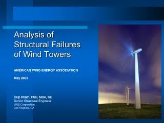
Wind Speed Interference From Callaway’s Aviation Beacon. Tim Waldron, Met Associates Kip Barbour, Callaway Plant October 9, 2003. Wind Speed Interference at Night.

E N D
Wind Speed InterferenceFrom Callaway’s Aviation Beacon Tim Waldron, Met Associates Kip Barbour, Callaway Plant October 9, 2003
Wind Speed Interference at Night In early April 2002 while validating Callaway Plant's meteorological data for the Annual Effluent Release Report, Tim Waldron of Met Associates, Inc. performed differential analysis of the Primary Tower 10M WS data compared to the Secondary 10M WS data. This analysis identified an approximate 3 m/s bias on the Primary Tower data, but only at night.
Illustrations of Differential Analysis The following slides provide some examples of the differential analysis used by Met Associates to identify the intermittent bias found in the Callaway Plant wind speed data.
Wind Speed Interference at Night • Tim speculated that the data was being affected by some kind of dusk-to-dawn circuitry at the Primary Tower shelter. • The only circuit controlled by a photocell at the Primary Tower was the single aviation beacon located at the top of the tower.
Single Strobe Aviation Beacon A Flash Technology FTB 310-4 strobe beacon was installed in September 1997.
Flash Technology Power Converter Cable to beacon Conduit to Photocell
Initial Troubleshooting • The I&C FIN team verified the beacon was the source of the interference by removing the 10 meter level cups and manually placing the beacon controls in night mode. • The strip chart recorder immediately jumped to ~3 m/s when the beacon was placed in night mode, and pulsed to ~5 m/s with each flash of the strobe.
Immediate Actions Taken • Manually placed the beacon controls in day mode. The strobe intensity is about 20,000 candles vs. 2,000 for night mode. • Wrote operability evaluation for WS with the beacon controls kept in day mode. • Contacted the “nearest flight service station” concerning strobe in day mode. • Wrote a “Night Order” for Operations.
Other Actions Taken • Submitted Special Report 2002-002 to the NRC. • Submitted an Operating Experience report through INPO.
Obstruction Marking and Lighting Federal Aviation Administration Advisory Circular, AC 70/7460-1K 23. Light Failure Notification b. Any failure or malfunction that lasts longer than thirty (30) minutes and affects a top light or flashing obstruction light, regardless of its position, should be reported immediately to the nearest flight service station (FSS) so a Notice to Airmen (NOTAM) can be issued. FAA’s website: www.faa.gov/ats/ata/ata400
Obstruction Marking and Lighting This report should contain the following information: • Name of persons or organizations • The type of structure • Location of structure • Height of structure above ground level • A return to service date. • FCC Antenna Registration Number, if app.
Obstruction Marking and Lighting 24. Notification of Restoration As soon as normal operation is restored, notify the same AFSS/FSS that received the notification of failure. The FCC advises that noncompliance with notification procedures could subject its sponsor to penalties or monetary forfeitures.
Investigation of Interference I contacted the following sources: • Innovative Flash, the contractor for Callaway’s cooling tower lights • Flash Technology, the beacon vendor • NUMUG e-mail list server
Innovative Flash Richard Schawba of Innovative Flash stated that he was only aware of one case where the flash head itself was creating an RFI field on a communications tower. They finally corrected the affect by installing a wire mesh around the flash head.
Flash Technology The Flash Technology representative stated that they do not endorse installing a mesh over their flash head.* He recommended moving the beacon cable away from the sensor cables. He stated that they had had similar problems on communications towers when the beacon cable was installed too close to the communications lines. *However, he also gave me the name and phone number of a competitor that sells a wire mesh made to fit their flash head…
Some NUMUG Feedback • “One, ensure that your signal cable and strobe cable are not co-located – they should especially not be tied to the same junction box. Two, make sure that your power source for the met system and for the strobe are separate. Both the met system and strobe should be grounded to your tower grounding network.” Matt Parker, W Savannah River Company
Some NUMUG Feedback • “If the Wind Speed data is only being biased from dusk until dawn, it may not be RFI. We had a problem years ago that required us to jumper out the surge suppression on the ground return from the tower sensors into the Climatronics computer. …we were getting errors on our wind direction sensors causing them to read lower than expected.” Tom Payne, Waterford 3
Some NUMUG Feedback • “I would imagine that if the cause of your problem is, indeed, RFI related proper grounding and shielding techniques for both the sensor and lamp cable as well as re-routing of the lamp power cable should mitigate it.” Bob Pickwoad, Palo Verde
Some NUMUG Feedback • “If I can add a note here, the shields need to be used. Send each of them through the cable run separately, and terminate them at the tower grid in the shelter (floating the sensors is important). Keep in mind that the analog translator circuits with the F460 system can pick up the RF, as well as the cable run.” Ralph Heistand, Turkey Point
Summary of Possible Causes • RFI from the beacon flash head. • EMI from the high voltage cable. • 60 Hz noise on tower ground. • Inadequate instrument cable shield grounding. • Shared a/c power source.
Cables at the Base of the Tower Beacon cable. Retired cables and waveguides. Instrument cables. 110 VAC power. Tower ground cable.
Possible Source of Interference 110 VAC in flex conduit Beacon cable Instrument cables
Review of Callaway TB Drawings • The drawings for the rack TBs showed the sensor shields grounded at the rack TBs. • The drawings for the tower TBs showed a jumper between the sensor shields and the tower ground. Possible ground loop? • The Climatronics vendor manual drawings showed them ONLY grounded at the rack.
Corrective Actions • FIN Electricians removed the jumper in the tower TBs to float the sensor shields. This did not fix the interference problems. • Planned work documents to move the beacon cable. Put on 12-week schedule! An Unexpected Discovery: The sensor cable shields were cut off at the rack TB, and were not grounded as shown on the rack drawings.
Corrective Actions • I&C FIN team re-lugged the sensor cables and grounded their shields at the rack. Grounding the sensor cable shields at the rack corrected the interference. • The work document to move the beacon cable was cancelled. • Health Physics and Met Associates had to resubmit several Effluent Release Reports