Download
1 / 31
310 likes | 703 Views
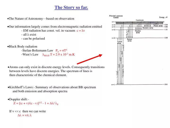
The Story so far. The Nature of Astronomy—based on observation Our information largely comes from electromagnetic radiation emitted - EM radiation has const. vel. in vacuum c = λν - all λ exist - can be polarised Black Body radiation

E N D
The Story so far. • The Nature of Astronomy—based on observation • Our information largely comes from electromagnetic radiation emitted - EM radiation has const. vel. in vacuum c = λν - all λ exist - can be polarised Black Body radiation -Stefan-Boltzmann Law PA = σT4 -Wien’s Law λMAX.T = 2.9 x 10⁻³ m.K • Atoms can only exist in discrete energy levels. Consequently transitions between levels have discrete energies. The spectrum of lines is then characteristic of the chemical element. Kirchhoff’s Laws:- Summary of observations about BB spectrum and both emission and absorption spectra • Doppler shift:- Z = [(c + v)/(c - v)]1/2 - 1 = / 0 If v c then we can write = v/c.
Stellar spectra-4 Here we see the atomic spectra for white light,sunlight and a series of elements. Note that the last spectra are for Na in emission and absorption. These spectra provide clear fingerprints for the chemical elements.
Molecular Spectra Molecule can rotate and vibrate so in addition to the discrete levels we have levels built on them with energies associated with them. We end up with closely spaced bands of levels built on each intrinsic level. [Rotations and vibrations] Vibrations:- Levels equally spaced Rotations:- Levels- E = (h/2)2.[I(I + 1)] 2 ζ where ζis the moment-of inertia
Information on Surface Temperature from Spectral Features. • Stars contain 75% H and 25% He plus small amounts of other elements. • At T = 6000K we have 3/2 kT eVs. This is similar to the binding energies of molecules.At this T they are broken up in collisions.As T rises spectral features related to molecules will disappear. • At low T atoms are neutral.As T increases collisions cause them to be ionised.At even higher T they become doubly then triply ionised etc. The spectra of ions differ from those of atoms. • We get a progression as T increases.At low T we have neutral atoms and molecules.The latter disappear and the former fade as T increases. We then get spectra from singly charged ions. At still higher T we get doubly charged ions. • H line is n = 2 to n =3 absorption line. The n = 2 level is first excited state in H.It is in middle of red part of spectrum. At low T very few H atoms are thermally excited so H is weak. As T increases so does occupation of n = 2 level and H becomes stronger. This absorption line reaches a peak at 10,000K. Beyond this many of the atoms are ionised and it fades again.
Summary of Stellar classification [Metals?] Temperature Remember-each of the classes is further subdivided 0-9 In the last few years there has been an attempt to introduce two more groups on the low temperature end. These are faint stars at low temperature, more and more of which are being classified. They are L and T. L stars have T between 1300 and 2500K. One sees a lot of metal hydride molecules such as CrH and FeH. T dwarves are even cooler and show a lot of methane. They are, in general, failed stars like Jupiter.
Classification of Stellar Spectra – Harvard Scheme TYPE Colour Approx T Main Characteristics Examples O Blue >25000K Singly ionised He in emission/absorption 10 LACERTA B Blue 11-25000K Neutral He in absorption RIGEL/SPICA A Blue 7.5-11000K H lines at max. strength for A0, decreasing thereafter SIRIUS/VEGA F Blue/white 6-7500K metallic lines become noticeable CANOPUS G White/yellow 5-6000K Solar-type, Absorption lines of metallic atoms/ions grow SUN K Orange/Red 3.5-5000K Metallic lines dominate ARCTURUS M Red <3500K Molecular bands of TiO noticeable BETELGEUSE Temp. Within each of these broad categories Annie Jump Cannon assigned sub-categories 0 – 9 with 0 being at the high T end. This is known as the Harvard scheme. It was funded by the wife of a wealthy doctor-Henry Draper and was carried out by a team composed largely of women [see photo of them in Universe, 6th Ed. Fig 19.10]. They included Williamina Fleming, Antonia Maury and Annie Jump Cannon. Later Cecilia Payne and Meghnad Saha showed that the catalogue the Harvard group created and classified was an indicator of surface temperature. Note:- The spectra reflect the temperature and composition of the surface and essentially the composition of the Star prior to formation since no nuclear reactions occur in the surface and there is little mixing with the interior A full classification should include Luminosity - See YERKES or MMK classification scheme.
UV N and O H2O Ionosphere O3 Altitude at which atmos. reduces intensity of radn by one-half. Proportion of light which arrives at sea level • Picture shows absorption of radiation by Earth’s atmosphere. There is strong absorption by N and O in the X-ray and gamma-ray regions, strong absorption by ozone in the UV,absorption of H2O in the infrared. Free electrons in the ionosphere reflect very long radio waves.
Telescopes • Astronomy arose from a) curiosity about the stars, b) desire to predict seasons and c) need to use it to navigate. • We can see 5,000-6,000 stars by eye in a clear sky. • There have been several “revolutions” in Astronomy. Astronomy 1)Galileo’s and Newton’s telescopes 2)Development of Radio-Astronomy followed by extension of observations to all parts of the spectrum. 3)The ability to place instruments in space to avoid the distorting effects of the atmosphere and the strong absorption at some wavelengths. Sir Isaac Newton(1642-1727)
Galileo’s and Newton’s telescopes • There are two types of telescope based on lenses(Galileo) and mirrors(Newton). • Light travels in straight lines. • Stars are a long way away and so light arriving from them is essentially in the form of parallel rays. • What happens when it crosses the boundary between two media.As we see in the figure its path is bent.The amount by which it is bent is given by Snell’s Law 1 n1 n2 2 Snell’s Law • If we write the index of refraction for a single medium as n1 = c/v then we can write n1.sin 1 = n2.sin 2 This is an empirical law that comes directly from observation.
• Galileo did not invent the refracting telescope but he used it to great effect.[see UNIVERSE ed.6,page 70] • One should note that with lenses and mirrors light follows the same path through the system in either direction. • a)With a converging lens a beam of light parallel to the axis of symmetry(optical axis) can be brought to a focus b)With a diverging lens the parallel beam appears to diverge from a pt. This unique point is called the FOCAL POINT and distance from this point to the centre of the lens is called the Focal Length(f). Note:- f = f() for lenses. Galileo Galilei (1564-1642)
Refracting Telescope • If we take the positive direction as the direction of the incoming light, then f is +ve for a converging lens,-ve for a diverging lens. • Lensmaker’s formula:- For a thin lens,assuming the surfaces are spheroidal, we can write 1 ( n - 1)[ 1/ R1 - 1/ R2] = f Where n is the index of refraction of the lens, R1 and R2 are the radii of curvature of the two surfaces. For convex lens R is +ve, and for a concave lens R is -ve.
Objectives of Telescope Design There are three main objectives of telescope design:- a)To maximise brightness of the image-to allow us to see faint objects. b)To resolve objects separated by small angles. c)To magnify the image so that objects can be seen to have size.
Image Brightness • The amount of light a telescope can gather is called the LIGHT GRASP. • For simple designs the light grasp is proportional to the cross-section of the aperture where the light enters. • Simple telescopes almost always have a circular aperture so the cross-sectional area is just ( D/2 )2 = D2/4 where D is the diameter of the opening. • Put simply LIGHT GRASP D2 • With the naked eye on a clear night we see 5,000-6,000 stars With a telescope( D = 20 cm ) we see 500,000 stars
Resolving Power • How well can one separate the images of two closely spaced objects? -It is dictated by diffraction of light at the aperture. • Figure shows diffraction at a single slit with a width b. Assuming a wavefront arrives at the aperture any ray passing through can be associated with a ray leaving the aperture a distance b/2 away.If they are /2 out of phase then destructive interference occurs.Then b/2.sin1 = /2 or sin1 = /b • If we divide the aperture into 4 parts then b/4.sin1 = /2 or sin1 = 2/b More generally sin1 = m/b where m = 1,2,3,4,---------- Thus we get darkness on the screen at these points and we get the diffraction pattern shown in the figure.
Rayleigh’s Criterion • The figure shows examples of the two overlapping diffraction patterns from two sources. • In two dimensions situation is more complicated.We get a bright, central spot called an AIREY disc. The eqns. for location of maxima and minima are the same but m is no longer a simple integer. The first two minima have m = 1.22 and 2.233. • Many possible criteria for resolution but most common is RAYLEIGH’S CRITERION = Two objects can be resolved if first minimum of one coincides with the centre of the Airey disc of the other.Assuming that sinm = m where m is the angular separation,then m = 1.22/b • In figure right and left are cases well resolved and unresolved.In the centre Rayleigh’s criterion.
Resolving Power •From Rayleigh’s Criterion m = 1.22/b and resolving power increases with increasing b, decreasing . In other words good resolution is achieved when is much smaller than the aperture so that light is not affected by it. • m does not improve without limit as we increase b -this is because of turbulence in the atmosphere. The local changes in atmospheric density cause refraction in many different directions. This causes stars to appear to twinkle. Since angular sizes of planets are much larger than scale of turbulence the distortions average out and they do not twinkle. Attempt to show how the Earth’s atmosphere behaves like a continuously varying,thick,weak lens. As a result the light from a star appears to enter the eye from different directions. It is grossly exaggerated here. Atmosphere Eye
Magnification • We only benefit from resolving power if the telescope has sufficient magnification as well. • Although we see a star as a point source it subtends a definite angle in the sky.Our design must make it appear to subtend a larger angle. • We define ANGULAR MAGNIFICATION = Apparent angle Actual angle • The picture compares the angular sizes of Venus, Moon and Sun. By chance the Sun and Moon both subtend 0.50 although the Sun is 400 times farther away.Venus subtends 0.0170 so to see Venus the same size as we see the Moon we need Ang.Magn.= 0.5/0.017 30
Refracting Telescope • Stars have a small angular size (exaggerated here). The converging lens forms an image at focal length f0. It would appear on a screen at this pt. • This image is the object for the second lens and is at the focal pt. Now the light will emerge as almost parallel rays but at a much larger angle( ) to each other.[Note:-The image at the end is inverted] • Simple geometry suggests that Angular Magnification = / =f0/fe • If we relax the condition that is small then eqn. is not strictly valid but if we adjust the lens separation a little we can get a focus and it remains a good approximation.
Difficulties with lenses and refraction • It is relatively easy to make a small refracting telescope. If f0/fe is large then we have good ang.magn.The sum of ( f0 +fe ) should equal the lens separation with a control to allow length variation to correct the focus. • However a large telescope of this type is difficult to make. - You need a large aperture to get the Light Grasp but it is very difficult to make large,high quality lenses. Even if you can there are problems supporting them within the telescope so that light passes through but the device does not sag. • In addition the focal length varies with wavelength although not a strong function. This is CHROMATIC ABERRATION. • It is negligible in a small telescope with thin lenses but becomes unacceptable in a large telescope.One possible cure is a compound lens which together give no variation with . This is impractical for a large objective lens.
The Reflecting Telescope • Here the concave mirror replaces the objective lens - to collect light and form first image. Light is reflected down the telescope back towards the object being viewed.A small flat mirror is placed inside the telescope to deflect the light to where it can be viewed.A flat mirror does not affect the image but does cut out some light and the image is a bit fainter. • Mirrors reflect light in same way independent of so problem of chromatic aberration is overcome. • Separation of mirror and lens remains the same,equal to ( f0 +fe ), but since the light is reflected back on itself the telescope is shorter, thus improving the mechanical stability. Mirrors can also be supported from behind.They can also be produced on a large scale with great accuracy. The surface is usually coated with Al-this can be removed and recoated.
Problems with Reflecting Telescopes • First main problem is choosing the shape of the mirror • Different mirror shapes give different problems depending on the task in hand. As we see on right of figure a spherical mirror suffers from SPHERICAL ABERRATION • As we see on the right the solution lies in the use of a PARABOLIC mirror. However this only works for axial rays and this limits the field of view. • Non-parallel rays are focused by curved mirrors in different positions. COMATIC ABERRATION
Problems with Reflecting Telescopes We looked earlier at the distortion of the image due to atmospheric turbulence. Variations in air temperature also have another effect - the mirror will distort a little due to variations in atmospheric temperature - the mounting of the mirror may also flex mechanically due to such variations. Active Optics – Every few seconds the mirror’s shape is adjusted to help keep the telescope at optimum focus and also aimed at the object of interest. Another limitation :- Clearly from what we saw about Light Grasp and angular resolution we would like to expand the filed of view i.e. make the entrance aperture larger However if we have a larger mirror it gets harder to cope with spherical aberration. One solution is a CATADIOPTRIC system. Note: A reflecting system is catoptric and a refracting systems is dioptric. This is a combination of the two.
Schmidt Camera • A CATADIOPTRIC system must be used to increase the field of view without the image suffering from spherical aberration. • SCHMIDT camera shown below uses a spherically shaped film plate placed inside and concentric with a spherical mirror. • A thin glass correction plate is placed over the front of the telescope. Refraction as the rays pass through the plate corrects spherical aberration but does not decrease the field of view available. • This instrument is able to take single focus photographs of the sky over several degrees.
After Before SN1987A- This picture was taken with a Schmidt camera. It shows a part of the sky in October 1987 before and after a supernova.
Adaptive Optics • Variations in atmospheric density cause the blurring of images by scintillation. • Here the light is directed into a feedback system in which a computer controls a small flexible mirror so that the image of a chosen bright star always appears as a point source. • The detector retains an image that is corrected for the effects of disturbances in the atmosphere for objects close to the chosen bright star in the field of view.
Problems with Reflecting Telescopes • Atmospheric effects - Turbulence causes “twinkling” Solution – active optics - adaptive optics - variations in mirror or mirror mounting light pollution - more and more street lights, disco lasers etc Solution-remote location Atmospheric absorption - solution-remote location on a mountain top well away from sources of light pollution. - dry to limit rain and clouds - calm - as high as possible
UV N and O H2O Ionosphere O3 Altitude at which atmos. reduces intensity of radn by one-half. Proportion of light which arrives at sea level • Picture shows absorption of radiation by Earth’s atmosphere. There is strong absorption by N and O in the X-ray and gamma-ray regions, strong absorption by ozone in the UV,absorption of H2O in the infrared. Free electrons in the ionosphere reflect very long radio waves.
Problems with Reflecting Telescopes • Atmospheric effects - Turbulence causes “twinkling” Solution – active optics - adaptive optics - variations in mirror or mirror mounting light pollution - more and more street lights, disco lasers etc Solution-remote location Atmospheric absorption - solution-remote location on a mountain top well away from sources of light pollution. - dry to limit rain and clouds - calm - as high as possible e.g Mauna Kea in Hawaii Telescope in orbit or on Moon/Mars etc in future
Astronomy beyond the visible • Observations are now possible at all wavelengths. Radio spectrum is not absorbed by the atmosphere. Incoming Radiation • Two ways of mapping the sky. -Move disk across the sky -Keep receiver fixed and scan reception freq. Receiver • m = 1.22 Here D 102 m and 104 - 106VISIBLE Som is much poorer than for a telescope in the visible. D Parabolic Metal dish • Solution lies in Interferometry.
Astronomy beyond the visible - 2 • Radio-Interferometry- - long baseline = many kilometres. Single so receivers have to lock into single phase co-ordinated with an atomic clock.Roughly aperture in a linear array is equal to length of the array. IR Radio waves • Atmospheric absorption is the problem in many parts of the spectrum.There are some windows in IR which allows observation in some elevated places with a warm dry climate. • Note that the eye is not the detector in any of the detectors we have looked at.Real detectors include a) Film, b) Photomultiplier tubes, c)Charged Coupled Devices = An array of small detectors on a Si chip. Electrical charge is proportional to light arriving.