Download
1 / 18
180 likes | 267 Views
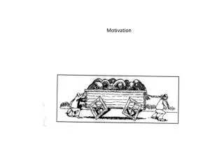
HO Scintillators in RPC Muon Trigger Conceptual design. J. F. de Trocóniz, UA-Madrid. Motivation General rule for muon triggers: Never neglect a possible backup reduction factor. It will always come back to you. Even if RPC trigger works just fine from the beginning one still wants to:

E N D
HO Scintillators in RPC Muon Trigger Conceptual design J. F. de Trocóniz, UA-Madrid Motivation General rule for muon triggers: • Never neglect a possible backup reduction factor. It will always come back to you. Even if RPC trigger works just fine from the beginning one still wants to: • Reduce rate in regions with only 4 or 3 RPC planes available. • Reduce pt thresholds as much as possible. HO should be better than any pre-scale.
Towers 8+9 represent 92% of the rate (pt> 10 GeV, || <1.24), but only 16% of the acceptance
HO Characteristics • 10 mm Bicron scintillator tiles positioned between coil and MB1 RPC • 1 plastic for Wheels ±1, ±2. 2 plastics separated by 15 cm iron slab in Wheel 0. • Covers the full MB1 system (barrel + overlap) up to || < 1.24 (Tower 9) • Typical cell size: 40 cm () × 50 cm () • Granularity: 0.087 () × 0.087 ()
HO matches well muon system in r- view (MB1) : 0.087 5 deg 16 RPC strips OK • Not that well in r- : 0.087 (HCAL standard tower size) detailed HO – RPC map needed
HO Readout • Standard HCAL readout: Fibers HPD (G=2500) QIE (T=25 ns) • 90% of energy in two samples (phase independent of HCAL) • More light: • Thicker plastics, • 4 WLS loops/tile, • shorter fiber path • Designed to give 10 pe / mip • Trigger: Energy-over-threshold bit
Test beam results Actual performance of HO system (Wheel 1 scintillators) measured at 2002 test beam (Jim Rohlf). • 6 pe/mip/plastic Gaussian noise at normal incidence. • 1.5 pe-equivalent/bucket • can be improved to 0.9 pe for “quiet” QIEs. Is this performance good enough? Can be achieved systematically at CMS?
HO Performance Simulated with CMSIM123 280 MeV/mip/plastic at normal incidence 6 pe 0.9 pe/bucket 64 MeV Geometrical acceptance: 93% Signal width dominated by photo-statistics. HO threshold at 1% tile occupancy 150 MeV (1 MeV deposited). Similar efficiency for 1.5 pe/bucket of noise, but 8 pe at signal peak, for EHO > 150 MeV (3% tile occupancy).
Electronic Noise Backgrounds p-p interactions (1034 cm-2 s-1): < 2 Hz/cm2 Neutron-induced conversions: < 10 Hz/cm2 (MB1 level) n-p elastic collisions: < 25 Hz/cm2 (for EHO > 150 MeV)
HO-RPC Mapping Equilibrium between large acceptance and simplicity (hardware implementation) Minimal Map Acceptance always larger than 90% (often much larger).
Trigger Algorithm HO provides extra “RPC plane”
Require HO confirmation for low-quality RPC coincidences Built-in high efficiency (low quality RPC muons are ~30%) Remarkable threshold stability (allows tuning at CMS)
Rate reduction • RPC noise trigger rates simulated using ORCA (50 Hz/cm2, nominal neutrons) • Large sample: 110 Mevents, corresponding to 4.4 s of LHC. • High quality noise trigger fraction much smaller than 1%. For 0.9 pe/bucket,EHO > 150 MeVReduction factor = 100 For 1.5 pe/bucket, EHO > 150 MeV Reduction factor = 30 Low-pt rates w/ HO comparable to high-pt w/o HO
Connecting Hardware(preliminary) • Processing of HO signals performed at HTR boards (4 boards/sector, 2 FPGA/board). • Provide energy-over-threshold programmable bit (possibly -dependent). • All OR-ing corresponding to the HO-RPC map also handled here • Input fibers organized according to constraints at HO end. • SLB cards organize HTR bits into bit streams, and transmit to RPC Trigger Boards using GOLs (32 bits/bx) • Output streams organized according to constraints at RPC end.
TRIGGER BOARD READOUT BOARD HCAL (HO) in RPC Trigger HCAL Front-end QIE GOL to Level-1 trigger QIE New 'Optical SLB' QIE HTR (Readout) Board Optical Tx SPLITTER Optical Tx 90 m @ 1.6Gbit/s S-link to DAQ up to 5 m LVDS @ 80MHz
Rx Rx Deser. Deser. Rx Rx Deser. Deser. Rx Deser. Rx Deser. Rx Rx Deser. Deser. Rx Rx Deser. Deser. Rx Deser. Rx Deser. Rx Rx Deser. Deser. Rx Rx Deser. Deser. Rx Rx Deser. Deser. Rx Rx Deser. Deser. Rx Rx Deser. Deser. Rx Rx Deser. Deser. Rx Rx Deser. Deser. 8-way fiber in Rx Rx Deser. Deser. Rx Rx Deser. Deser. 8-way fiber in Rx Rx Deser. Deser. HTR Configuration for HO Total of 48 calorimeter channels per HTR SLB SLB FPGA P1 Outputs to RPC Crate SLB SLB SLB P2 SLB DAQ out FPGA Front-end data inputs 8 8
Example of cabling scheme satisfying all constraints at HO and RPC ends
Conclusions Investigating how to incorporate HO into RPC trigger:Geometrical integration, RPC+HO extended algorithm, basic lines of hardware implementation established. If HO performance at 2002 test beam achieved systematically at CMS RPC trigger rate reduced by 100. Efficiency O(90%) stable as a function of HO energy threshold (allows tuning). Implications much more important in case RPC noise can be reduced to 5 Hz/cm2 consider HO to improve efficiency (less restrictive algorithms, tower 6, “classic” 3/4). HO is now part of the L1 Trigger Baseline