Download
1 / 54
690 likes | 1.11k Views
TV Systems. Content: CRT scanning composite video signal colour systems satellite orbit earth station satellite TV. CRT principle. Electrostatic deflection. CRT principle. Electromagnetic deflection: use of magnetic energy to deflect electron beam both vertically & horizontally

E N D
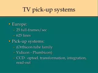
TV Systems Content: • CRT scanning • composite video signal • colour systems • satellite orbit • earth station • satellite TV
CRT principle Electrostatic deflection
CRT principle • Electromagnetic deflection: use of magnetic energy to deflect electron beam both vertically & horizontally • practically all TV display devices use electromagnetic deflection
CRT principle Deflection yoke: two sets of coils for generating electromagnetic deflection both vertically & horizontally
CRT principle Beam focusing: an electromagnetic focusing coil is placed around the neck of a CRT
Scanning process Deflection process: positions the electron beam on the inner surface of CRT Scanning process: controls the deflections of electron beam so as reconstruct images on the screen Rectilinear scanning: two separate scanning procedures occurs simultaneously, • vertical scanning • horizontal scanning
Simplified scanning Simplified scanning • lines are scanned sequentially • dashed lines represent beam retrace • beam retrace occurs very rapidly & is blanked by disabling the beam • simple but required wide BW • not used in TV receivers
Interlaced scanning • Each completed picture is divided into two fields: • ODD field • EVEN field • Each field is scanned one after another: • ODD field => EVEN field => ODD field…. • Two interlaced fields make up one frame • frame rate: 60/2 or 30Hz (50/2 or 25Hz for H.K.) • Complicated scanning • required half BW of simplified scanning
New development Progressive scanning Interlaced scanning Horizontal frequency: 50Hz => 100Hz HDTV (High Definition) : double resolution
Aspect ratio • Defined as the width versus the height of raster • typical values 4:3 & 16:9 • pictures then more pleasing to eyes Standard 4:3 aspect ratio
Synchronization • Why synchronization is needed ? Electron beam scanning the CRT surface of TV receiver must be exactly follow the video signal sent from a station. • Sync pulses are included as part of a video signal • Two types of sync pulses: • horizontal sync pulses • vertical sync pulses • Sync pulses trigger the flyback of electron beam at the end of lines or end of a field
Synchronization • Vertical sync • Horizontal sync
BW of video signal Max BW is required when sending patterns of alternate black & white vertical lines
BW of video signal No. of lines =625; Aspect ratio 4:3 Pixel per line = 625x4/3 = 833 Horizontal freq = 625x25=15,625Hz Scan one horizontal line needs 1/15625 sec. or 64µs t=(64/833)x2µs=0.154µs Thus BW=1/t = 6.5MHz (practical BW:5.5MHz)
B&W composite video signal Control beam intensity Horizontal sync pulse
B/W TV block diagram Video detector : demodulates the video signal (AM) Video amplifier: a wide band amplifier used to amplify the video signal to drive the cathode of CRT Sync separator: separates the vertical sync and horizontal sync from the video signal High voltage supply: generates an EHT voltage to drive the anode of CRT Horizontal oscillator: controls the horizontal deflection of electronic beam Vertical oscillator: controls the vertical deflection of electronic beam
Colour composite video signal Y signal • luminance signal (control brightness of picture) • monochrome receiver uses Y to display B/W image • Y=0.59G+0.3R+0.11B R: Red colour voltage, G: Green colour voltage, B: Blue colour voltage I signal • formed by (R-Y) • modulates 3.58MHz subcarrier directly Q signal • formed by (B-Y) • modulates a 90º shifted 3.58MHz subcarrier
NTSC colour system • NTSC stands for National Television Systems Committee • Colour TV in US, Japan, Korea, and the Philippines used NTSC system • Compatible with monochrome receiver • Consists of : • luminance signal Y (control brightness) • colour signal I-Q (chrominance) • 3.58MHz subcarrier (suppressed at transmitter) • line rate:15,750Hz • field rate: 60Hz • 525 lines
Colour composite video signal used as a reference for colour demodulation
PAL colour system • Phase Alteration by Line • TV broadcast standard developed in Germany and used in the H.K.,U.K, and most of Europe, Africa, Australia,etc. • PAL produces interlaced 625-line, 25 frames/second
History of satellite Comm. • Before 1960s, most long-range communications via HF band • HF band was overcrowded & unreliable • Satellite communication provides: • greater communication capacity • higher quality • better reliability • In 1960s, a series of passive satellites were launched • Echo satellites like large metal balloons that reflected radio waves
History of satellite Comm. • Placed in low orbits • Active satellites were then launched • an active broadband repeater • signal from earth station is converted to another freq & sent down to the earth • a stronger signal can be received at the earth compared with passive satellite • but the satellite can’t be accessed at any time since it was placed at low orbit • Today, communication satellites are placed in synchronous orbits
Satellite orbits When satellite is in orbit: force due to gravity F1 = centrifugal force F2
Freq. band for sat. comm. Notice that the downlink freq < uplink freq since attenuation depends on freq: lower freq => lower attenuation => lower tx power needed for downlink
Satellite orbits • Gravitational force is proportional to distance • Centrifugal force is proportional to distance & velocity • The farther from earth, the slower the orbital speed • The closer to earth, the faster the orbital speed • low-altitude sat travels at higher speed • low-altitude sat completes one orbit faster due to higher speed and shorter distance • low-altitude sat appears to be moving when viewed from the earth
Types of orbit • Low Earth Orbit (LEO) • height < 1600km • round the earth in less than 2 hours • complicated tracking mechanism • used in early days of sat due to limited launching power • applications: - maritime & aviation navigation, weather forecasting & surveillance
Types of orbit • Geostationary(Synchronous) Orbit (GEO) • height : 35,860km from equator • orbital period: 24 hours • no tracking of antenna required • sat appears to be stationary observed from the earth • good for telecommunication, e.g. voice • worldwide coverage by 3 sat
Look angle The coordinates to which an earth station antenna must be pointed to communicate with a sat are called look angle: • azimuth (Az) • elevation (El)
Earth station Collection of equipment on the surface for communicating with the satellite, may be: • fixed • ground mobile • maritime • aeronautical
Earth station Desired characteristics: • high gain in the direction of wanted signals • low gain in the direction of unwanted signals • low noise for receiving system • high antenna efficiency • continuous satellite pointing • minimum performance variations caused by weather • availability of power resources
Antenna • A ‘dish’ to collect very weak microwave signals to a focus point. • size depends on of signal • made from steel, aluminium or fiberglass embedded reflective foil => highly reflective surface
Transmitter Vary from simple single transmitter of few Watts to multi-channel transmitters using 10-kW (water cooling needed) • Klystron • 500~5000W output power • small bandwidth, 40MHz • medium cost • Travelling Wave Tube (TWT) • 100~2500W output power • large bandwidth, 500MHz • high cost
Receivers • signal from sat is received via an antenna • signal is then amplified by LNA (Low Noise Amplifier) • down-converted to lower frequency immediately before sending to receiver equipment via coaxial cable for demodulation
Diplexer • used to separate the transmitted signal & received signal since the same antenna is used for transmission & receiving • dual polarization (vertical & horizontal) to allow frequency reuse
Tracking • to ensure the precise pointing of a narrow beamwidth antenna • automatic • determine velocity of sat • small earth stations with large beamwidth => no tracking
Advantages of sat comm. • Signals from sat cover large area (footprint) • determined by beamwidth of transmitting antenna • only 3 sat to cover almost entire earth surface • distance insensitive cost • much cheaper for long distance comm. & regional broadcasting
Advantages of sat comm. • high reliability • EM wave propagation only slightly affected by atmosphere • flexibility • provide multi-channel TV, thousands of telephone channels & data transmission
Limitations of sat comm. • sat transmitter power • limited by available power (solar) in sat • limited by payload of launch vehicle • sat receiver sensitivity • sat antenna intercepts only a small radiated energy • sat availability • only sat at geostationary orbit can provide continuous service
Limitations of sat comm. • long transmission time delay: time delay=distance/velocity of light distance = 2 X 36,000km (round trip) velocity of light = 3X10⁸m/s time delay = 0.25s time delay causes echo in telephone communication. • Limited life-time: approx. 10 years