Download
1 / 37
370 likes | 548 Views
THEMIS Electric Field Instrument (EFI) Instrument CDR The THEMIS EFI Team. Outline. Personnel and Organization Summary of EFI Status at MPDR Requirements, Specifications, and Design Compliance Design Overview Top-Level Design Design Drivers and Compliance DC Error Budget AC Error Budget.

E N D
THEMIS Electric Field Instrument (EFI) • Instrument CDR • The THEMIS EFI Team
Outline • Personnel and Organization • Summary of EFI Status at MPDR • Requirements, Specifications, and Design Compliance • Design Overview • Top-Level Design • Design Drivers and Compliance • DC Error Budget • AC Error Budget
Personnel and Organization • Organizational Chart (all UCB unless noted): • Prof. F. Mozer (EFI Co-I). • Drs. J. Bonnell, G. Delory, A. Hull (Project Scientists) • P. Turin (Lead ME) • Dr. D. Pankow (Advising ME) • B. Donakowski (EFI Lead ME, SPB, Facilities) • R. Duck (AXB ME) • D. Schickele (Preamp, Sensor Cables, Facilities ME) • G. Dalton (SPB, EFI GSE Mechanical) • S. Harris (BEB Lead EE) • H. Richard (BEB EE) • J. Lewis, F. Harvey (GSE) • Technical Staff (H. Bersch, Y. Irwin, H. Yuan, Wm. Greer (UCLA), et al.) • R. Ergun (DFB Co-I; CU-Boulder) • J. Westfall, A. Nammari, K. Stevens (DFB SysE, EE; CU-Boulder) • C. Cully (DFB GSR; CU-Boulder)
EFI Status at I-CDR • Requirements and Design: • The current EFI design meets Mission and Instrument requirements. • The design is complete. • One new requirement (CG positioning) has been imposed post-PDR. • Procurement: • All long-lead items have been procured in sufficient quantities to allow for ETU and initial FLT production: • EEE parts ordered; rad testing of required parts arranged. • SPB and AXB mechanical items (custom wire cable, stacers, actuators, motors) are in-house, or on order with expected delivery on schedule for FLT build up. • Vendors for mechanical and electrical fab identified through ETU production Dec ’03 through Mar ’04. • Personnel: • Team is complete: • All design engineering positions filled. • One FT MTech position filled Mar ’04; two PT Mtech positions filled internally by personnel transitioning over from STEREO. • Assembly and Test: • ETUs of all major elements have been assembled and partially or largely tested. • Testing will be completed by M-CDR (June 15-16 ’04).
RFA and Design Trade Closure • RFAs from I-PDR and M-PDR all closed out: • ESC Spec is on Rev. D1; includes detailed specs on the requirement and methods to achieve it; ESC roster developed in Feb ’04, allowing close collaboration between Swales and UCB on problem areas and mitigation techniques. • EMI Spec completed Mar ’04. • Detailed Instrument I&T plan under development as part of ETU Testing; synthesized from Polar, Cluster, etc. • Open Design Trades from PDR closed out: • Boom lengths set at 50/40/7.67 meters tip-to-tip based on CBE of Probe mass properties and std. GSFC and UCB dynamic stability requirements and boom mode resonance keep-outs. • Ti-N chosen over DAG-213 for SPB sensor coating. • Heritage brushed motor chosen for SPB deploy. • Braid biasing selected, and Distal Braid length set at 3 m. • DAC implementation on BEB chosen (ADC5544), and bias offset range of +/- 40 V maintained. • EFI filters on DFB chosen to be Bessel-type. • Others to be covered in individual presentations.
EFI Block Diagram • A High-Input Impedance Low-Noise Voltmeter in Space sheath sensor preamp Floating ground generation BIAS USHER Bias channels GUARD VBraidCtrl VBraid BRAID Vref
Top-Level Design (1) • Diagram of THEMIS EFI Elements
Top-Level Design (2) • Description of THEMIS EFI Elements • Three-axis E-field measurement, drawing on 30 years of mechanical and electrical design heritage at UCBSSL. • Closest living relatives are Cluster, Polar and FAST, with parts heritage from CRRES (mechanical systems, BEB designs, preamp designs).
Top-Level Design (3) • Description of THEMIS EFI Elements • Radial booms: • 22-m cable length (up to 50 m tip-to-tip deployed; SPB-X to be deployed to 50 m, SPB-Y to be deployed to 40 m). • 8-cm dia., Ti-N-coated spherical sensor. • 3-m, 0.009-inch dia. fine wire to preamp enclosure. • USHER and GUARD bias surfaces integral to preamp enclosure. • BRAID bias surface of 3-m length inboard of preamp (common between all 4 radial booms). • Sensor is grounded through 10 Mohm resistance when stowed, providing ESD protection and allowing for internal DC and AC functional tests. • External test/safe plug (motor,door actuator,turns click, ACTEST) to allow for deploy testing/safeing and external signal injection.
Top-Level Design (4) • Description of THEMIS EFI Elements • Axial booms: • 2.8-m stacer with ~1-m DAG-213-coated whip stacer sensor. • Preamp mounted in-line, between stacer and sensor. • USHER and GUARD bias surfaces integral to preamp enclosure. • No BRAID bias surface. • Sensor is grounded through 10 Mohm (TBR) resistance when stowed, providing ESD protection and allowing for internal DC and AC functional tests. • External test/safe plug (deploy actuator, ACTEST) to allow for deploy testing/safeing and external signal injection.
Top-Level Design (5) • Performance Specification • EFI radial sensor baseline will be 40 or 50 m, tip-to-tip. • EFI axial sensor baseline will be 7.7 m, tip-to-tip. • 16-bit resolution. • Spacecraft potential: +/- 60 V, 1.8 mV resolution, better than 46 uV/m resolution (allows ground reconstruction of E from spacecraft potential to better than 0.1 mV/m resolution). • DC-coupled E-field: +/- 300 mV/m, 9 uV/m resolution. • AC-coupled E-field: +/- 50 mV/m, 1.5 uV/m resolution. • AKR log(Power) channel: <= 70 uV/m amplitude, 100-500 kHz bandwidth.
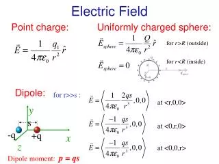
DC Error Budget (1) • The estimated electric field along the direction between the two probes is E=(v1-v2)/2L. • Errors arise from and are mitigated by: • Errors in baseline (L). • Errors in v1 and v2; eg. (v1-v2) or each individually.
DC Error Budget (2) • Errors in baseline (L). • Control boom length to 1%, trim deploy length to 4-cm accuracy. • Increase fine wire length to reduce boom shorting effect (observed up to 20% on Cluster; predicted 5% on THEMIS (better Lf/L)). • SPB-X and SPB-Y have different boom lengths, allowing for examination of L-dependent systematic errors on spin-period time scales (similar to Polar).
DC Error Budget (3) • Errors in v1 and v2; eg. (v1-v2) or each individually. • Use TI-N coating on sensors (DAG-213 on AXB) for uniform photoemission. Keep all sensors clean pre-launch. • Use high-impedance preamp (1012 ohm) to reduce DC attenuation. • Current-bias sensor to reduce sheath impedance and susceptibility to photoemission asymmetries (20-100 Mohm typ.). • Mount sensor on fine wire and reduce emission area of preamp to reduce magnitude and effect of asymmetric photoemission (3-10 times smaller than Cluster). • Use USHER and GUARD surfaces to control photocurrents to sensor (>= 20-V bias range, well above bulk of photoelectron energies). • Use fine wire and BRAID bias surface to reduce cold plasma wake effects (scale with D/L or 1/L; roughly equivalent to Cluster). • Enforce 1.0 to 0.1-V electrostatic cleanliness specification on THEMIS to reduce SC potential asymmetry effects to < 0.1 mV/m on all axes.
AC Error Budget (1) • EFI Spectral Coverage and System Noise Estimates Maximum Spectra (DC-Coupled) 1/f3 1/f flat CDI BBF AKR band 1-LSB Spectra (DC-Coupled) Preamp and Rbias Current Noise Preamp Voltage Noise axial radial 10-Hz Ac-coupled roll-in Spin frequency 4-kHz Anti-aliasing roll-off
AC Error Budget (2) • RE02 BB Limits set to give S/N of > 3 for expected AKR amplitudes. • RE02 NB limits set to drop equivalent BB spectral density below expected amplitudes below 4 kHz on SPB.
AC Error Budget (3) • 7.5 pF input capacitance of preamp has significant effect on gain above 100 Hz: • SPB AC gain is 0.65. • AXB AC gain is 0.45. • Rolloff frequency from DC to AC gain (resistive to capacitive coupling) is predominantly controlled by sheath resistance, which is under direct control via sensor bias current.
Summary of EPR Findings • Radial Boom design (1,2,3,9; Draft findings, 3 Nov 2003): • Dynamic stability issues (spin/trans MOI ratio) (Bus EPR) • Dual-length/longer-length designs • Axial Boom design (6,10): • Deploy force margin • Length vs. noise margin, whip vs. sphere sensors. • Attitude information and jitter requirements (14). • Miscellaneous mechanical findings (15,18,5): • Deploy sequence modeling. • Boom deployment temperature. • SPB miter gear life testing. • Hot parts and thermal stresses • Gain and Filter Specifications of EFI and SCM on DFB (4,8,12). • BEB FPGA specification and programming (20). • Preamp electro-mechanical design (11). • Electrostatic Cleanliness Specification (RFA UCB-8)(7,17). • EMI/EMC Specification (RFA UCB-9)(13). • Detailed I&T plan development (RFA UCB-10)(19).
EPR Findings—Radial Booms • Dynamic stability issues: • Bus and Instrument team analysis of dynamic stability not in accord; question is proper spin/transverse MOI ratio for non-rigid boom systems on THEMIS. • Swales analysis indicates shorter AXB (60%) or longer SPB required to achieve stable configuration (Bus EPR finding). • Longer-length/Dual-length designs (science-driven): • 56-m (2x(25+3)m system) tip-to-tip SPB possible with current mechanical design. • Direct improvement in DC error budget (30%). • Allows for dual-length (21/28 m) system that would allow the detection of ES wake effects (not mission critical, however). • Mass hit (56 g/SPB) for 7-m cable addition; fuel hit (~60%, 452 g increase) for final spin up. • Resolution: • Must be resolved by Jan ’04 (EFI F1 Cable Assy); Cable Assy schedule margin allows push back to Apr ’04, if necessary. • Dynamic stability analysis is ongoing at Swales and UCB.
EPR Findings—Axial Booms • Deploy force margin and AXB length repeatability: • AXB design may not have enough deploy force margin to ensure dL/L = 1% repeatability of deploy length. • Resolution: AXB ETU testing (Feb ’04). • Length vs. Noise Margin; whip vs. sphere sensor response • Current AXB length (~9-m effective, 10-m tip-to-tip) allows only factor of 3 S/N margin at 4 kHz (CBE of system noise level). • SC perturbations will strongly affect DC E-field in AXB (several mV/m, dependent upon SC potential (plasma conditions). • AXB whip sensor may have different response para/perp to B than SPB sphere+wire sensor. • Resolution: AXB length can not be reduced significantly without compromising 3D AC measurement. AXB lengths will be trimmed based on simulation results to reduce DC offset due to SC potential (final length Feb ’04 (AXB F1 Mach)). Literature on antenna response to be investigated to determine significance of whip vs. sphere effect (no mitigation planned; different capacitance of SPB and AXB sensors already known, and part of electrical Calibration plan).
EPR Findings—Attitude • Attitude knowledge and jitter requirements are modest, and achievable by Bus and Instrument designs. • 5.6 degree (10%) knowledge required; better than XXX degrees (YYY%) achieved via post-processing of FGM and EFI data. • Better than 3-degree accuracy and jitter in spin phase required for accurate on-board spin fits of E-field data; current IDPU design provides XXX degrees.
EPR Findings—Misc. Mech. • UCB should initiate kinematic and dynamic modeling of the boom deploy sequences. • Resolution: Kinematic model of boom deploy already exists (Th_booms3d.xls; D. Pankow) at UCB as tool for understanding timing, spin-up requirements, mechanical loads, boom/SC modes, coriolis displacements, etc. • Resolution: Algor product will be taken under advisement as part of on-going resolution of dynamic stability question (see Radial Booms; Jan ‘04). • Boom deployment temperature range should be defined. • Resolution: Boom deployment temperature range will be defined as part of I&T test flow (Dec. ’03-Jan. ‘04). • SPB miter gear life testing under worst-case load required. • Resolution: Such testing will be included in SPB I&T test plan (Dec ’03 – Jan ’04).
EPR Findings—Gain/Filter • DC/AC-coupled dynamic range and solitary waves • Large-amplitude (>=100 mV/m) solitary waves have been observed at frequencies from 1-1000 Hz on Polar and Cluster in the THEMIS observation region. Such waves will saturate the AC-coupled (10 Hz-6 kHz) E-field channels with a dynamic range of +/- 50 mV/m. • Resolution: Other channels can handle the large-amplitude events, although not simultaneously. DC-coupled (0-4 kHz) channels have a dynamic range of +/- 300 mV/m. Dc-coupled sphere/whip voltages have +/-60-V range (3 V/m on SPB, ~13 V/m on AXB). AC-coupled gain may be reduced to allow higher rate sampling of large-amplitude signals (TBR, Nov-Dec ’03, DFB ETU design). • Filter specifications • SCM channels use Butterworth, EFI uses Bessel. Difference means non-trivial phase differences and time-domain responses over entire 0-4 kHz range, maximizing between 1-4 kHz, preventing direct comparison of time-domain signals. • Resolution: Trade between filter types underway (TBR, Nov-Dec ’03, DFB ETU design).
EPR Findings—BEB FPGA • BEB FPGA specification and programming • Resolution: BEB FPGA requirements are modest and now well-defined (CDI interface, DAC control, Analog housekeeping), and common to most IDPU boards, allowing FPGA programmer (R. Abiad, UCB) to work on design and programming within BEB ETU schedule (Build/Test, Dec ’03).
EPR Findings—Preamp • Bootstrapping and guarding of preamp inputs • Bootstrapping and guarding of preamp electronics in the current electromechanical design should be reviewed. Potentials of all conductors need to be defined (can, shields, etc.). • Resolution: Current design does not include input guard, based on estimated input capacitance of preamp enclosure. Preamp ETU Assy and Test begins early Dec ’03 to characterize input capacity, and allow for changes and re-evaluation before FLT fabrication begins (Jan ’04).
EPR Findings—ESC • Electrostatic Cleanliness Specification and Enforcement • Resolution: Rev. B of the THEMIS ESC Specification has been posted for review and will be signed off in Nov ’03. It is is available via the THEMIS ftp site (URL), and includes a complete specification of electrostatic cleanliness requirements as well as verification procedures. The specification sets a 1-V potential uniformity requirement under an 8 nA/cm2 current density, with 0.1-V potential uniformity as a goal (see DC Error Budget for discussion).
EPR Findings—EMI/EMC • Electromagnetic Interference/Cleanliness Specification • Resolution: A Draft of the THEMIS EMI/EMC Specification has been posted for review and will be signed off in TBD. This specification is modeled on that for the FAST mission, adapted to the instrument properties on THEMIS (SCM/EFI system noise levels and expected wave amplitudes). Testing and verification of compliance with EMI/EMC TBD, and requires some work, due to low frequencies of interest (0-4 kHz).
EPR Findings—I&T Plan • I&T test flow needs to be defined to include development, ETU, qualification and acceptance testing. • Resolution: An EFI I&T plan will be developed in Dec ’03 to support qualification and acceptance testing of the EFI ETU in Jan-Mar ’04.