Download
1 / 7
70 likes | 163 Views
A 5 m -5 m 0 m. A 5 m 5 m 10 m. A 5 m 0 m 5 m. B 8 m -8 m 0 m. B 8 m 2 m 10 m. B 8 m -3 m 5 m. Hp Hz Ht. Hp Hz Ht. Hp Hz Ht. Ref is pool bottom. dHt = HtA - HtB = 0 m. 1. Hydraulic Gradients: Determination of direction of groundwater flow.

E N D
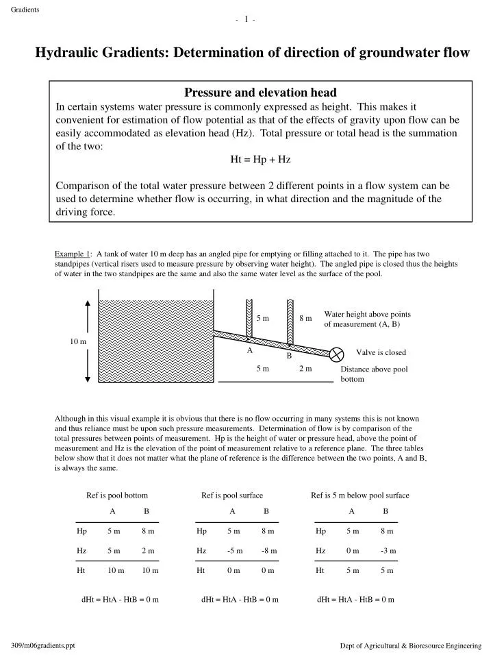
A 5 m -5 m 0 m A 5 m 5 m 10 m A 5 m 0 m 5 m B 8 m -8 m 0 m B 8 m 2 m 10 m B 8 m -3 m 5 m Hp Hz Ht Hp Hz Ht Hp Hz Ht Ref is pool bottom dHt = HtA - HtB = 0 m 1 Hydraulic Gradients: Determination of direction of groundwater flow Pressure and elevation head In certain systems water pressure is commonly expressed as height. This makes it convenient for estimation of flow potential as that of the effects of gravity upon flow can be easily accommodated as elevation head (Hz). Total pressure or total head is the summation of the two: Ht = Hp + Hz Comparison of the total water pressure between 2 different points in a flow system can be used to determine whether flow is occurring, in what direction and the magnitude of the driving force. Example 1: A tank of water 10 m deep has an angled pipe for emptying or filling attached to it. The pipe has two standpipes (vertical risers used to measure pressure by observing water height). The angled pipe is closed thus the heights of water in the two standpipes are the same and also the same water level as the surface of the pool. Water height above points of measurement (A, B) 5 m 8 m 10 m A Valve is closed B 5 m 2 m Distance above pool bottom Although in this visual example it is obvious that there is no flow occurring in many systems this is not known and thus reliance must be upon such pressure measurements. Determination of flow is by comparison of the total pressures between points of measurement. Hp is the height of water or pressure head, above the point of measurement and Hz is the elevation of the point of measurement relative to a reference plane. The three tables below show that it does not matter what the plane of reference is the difference between the two points, A and B, is always the same. Ref is pool surface Ref is 5 m below pool surface dHt = HtA - HtB = 0 m dHt = HtA - HtB = 0 m
A A A B B B Hp Hz Ht Hp Hz Ht Hp Hz Ht Water height above points of measurement (A, B) 3 m Ref is as shown on diagram 7 m A B Distance above reference plane 25 m 22 m dHt = HtA - HtB = 2 Example 2: Determine whether flow is occurring and in what direction for the diagram below: Water height above points of measurement (A, B) 2 m 10 m 2 m A B 5 m 2 m Distance above pool bottom Ref is pool bottom Ref is 20 m above poolbottom dHt = HtA - HtB = dHt = HtA - HtB = Example 3: Determine whether flow is occurring and in what direction for the diagram below:
A V t Example 1; Piezometers in a groundwater aquifer. Both piezometers are the same depth. z Ref plane (z = 0) is 2 m below piezometer bottoms x ref plane (x = 0) is through point A A B 5 m 5 m A B Hz Hp Ht 2 m 5 m 7 m 2 m 5 m 7 m 100 m z = 0 m x = 0 m dHt dHx HtA - HtB HxA - HxB 7 m - 7 m 0 m - 100 m 0 m -100 m i = = = = = 0 No flow as total pressures are the same. 3 Liquid transport in porous materials (laminar flow) q = - K i Flow (q) is proportional (K) to the hydraulic gradient (i) and will occur in the direction of (-) decreasing potential Flux (q, m/s) Volume of flow per cross-sectional area of media per unit time; q = V A-1 t-1 = m3 m-2 s-1 = m/s Flux is a velocity term. Hydraulic conductivity (K, m/s) is a function of • the ability of the media to conduct (permeability) and • the ability of the liquid to flow (fluidity) Hydraulic gradient (i, m/m) is the change in pressure over a distance: i = dHt/dx where dHt = HtA - HtB, the change in total pressure between points A and B, Ht = Hp + Hz, where Hp is the water pressure and Hz is the position of the point relative to the reference plane (z = 0) dx = HxA - HxB, the distance between points A and B in a horizontal plane, and 'H' represents pressure as a hydraulic head of water measured as height (m or cm). Calculation of hydraulic gradient; horizontal flow
A B Hz Hp Ht 2 m 8 m 10 m 2 m 5 m 7 m Example 3 (same as 2, but z ref changes); Piezometers in a groundwater aquifer. Both piezometers are the same depth. z Ref plane (z = 0) is at ground surface x ref plane (x = 0) is through point A z = 0 m 15 m 8 m 5 m A B A B 100 m Hz Hp Ht -15 m 8 m -7 m -15 m 5 m -10 m x = 0 m dHt dHx HtA - HtB HxA - HxB -7 m - -10 m 0 m - 100 m 3 m -100 m i = = = = = -0.03 m/m Flow occurs from high pressure to low pressure (A to B). The negative sign of the gradient indicates flow to the left in the x-axis. Note: although z-ref plane changed position and thus the total pressures changed the gradient remained constant in sign and value 4 Hydraulic gradient Calculation of hydraulic gradient; horizontal flow Example 2; Piezometers in a groundwater aquifer. Both piezometers are the same depth. z Ref plane (z = 0) is 2 m below piezometer bottoms x ref plane (x = 0) is through point A 8 m 5 m A B 100 m z = 0 m x = 0 m dHt dHx HtA - HtB HxA - HxB 10 m - 7 m 0 m - 100 m 3 m -100 m Flow is from high to low pressures (from A to B) or from left to right as indicated by the negative sign i = = = = = -0.03 m/m
z = 0 m dHt dHz HtA - HtB HzA - HzB 10 m - 10 m 7 m - 2 m 0 m 5 m i = = = = = 0 m/m z = 0 m dHt dHz HtA - HtB HzA - HzB 10 m - 5 m 7 m - 2 m 5 m 5 m i = = = = = 1 m/m 5 Hydraulic gradient Calculation of hydraulic gradient; vertical flow Example 1; Piezometers in a groundwater aquifer. Piezometers are at 2 different depths, one above the other. z Ref plane (z = 0) is 2 m below piezometer B 3 m Hz 7 m 2 m Hp 3 m 8 m Ht 10 m 10 m A There is no flow as the hydraulic gradient is '0'. 8 m A B 7 m B 2 m Example 2; Piezometers in a groundwater aquifer. Piezometers are at 2 different depths, one above the other. z Ref plane (z = 0) is 2 m below piezometer B 3 m Hz 7 m 2 m Hp 3 m 3 m Ht 10 m 5 m A There is flow as the total pressure heads are different. Flow is from high to low (A to B). Flow is down as indicated by the postive gradient. A B 7 m 3 m B 2 m
z = 0 m dHt dHz HtA - HtB HzA - HzB 8 m - 10 m 7 m - 2 m -2 m 5 m i = = = = = - 0.4 m/m z = 0 m dHt dHz HtA - HtB HzA - HzB -4 m - -2 m -5 m - -10 m -2 m 5 m i = = = = = - 0.4 m/m 6 Hydraulic gradient Calculation of hydraulic gradient; vertical flow (continued) Example 3; upward flow Piezometers in a groundwater aquifer. Piezometers are at 2 different depths, one above the other. z Ref plane (z = 0) is 2 m below piezometer B 1 m Hz 7 m 2 m Hp 1 m 8 m Ht 8 m 10 m A There is flow upwards as indicated by the lower total pressure at A and by the negative hydraulic gradient. 8 m A B 7 m B 2 m Example 4; same as #3 but ref plane is moved. Piezometers in a groundwater aquifer. Piezometers are at 2 different depths, one above the other. z Ref plane (z = 0) is at groundsurface. 5 m 1 m Hz -5 m -10 m Hp 1 m 8 m Ht -4 m -2 m 8 m A Flow is still upwards. Location of the reference plane has nothing to due with the sign nor the value of the hydraulic gradient. 10 m A B B
z = 0 m Change in elevation from A to C, 5 m 200 m 200 m 7 Hydraulic Gradients; Groundwater flow in an hillslope. Piezometer A B C D E Depth beneath soil surface (m) 9.0 6.0 6.0 4.0 2.0 Water height (from bottom of piezometer, m) 4.0 1.2 3.5 3.0 0.5 x = 0 m 3 m B E C D A Flow Direction A and B A and C C and D D and E Hydraulic gradients iA-B iA-C iA-D iD-E Hz (m) + Hp (m) = Ht (m) Find: A B C D E