Download
1 / 43
430 likes | 745 Views
Project: IEEE P802.15 Working Group for Wireless Personal Area Networks (WPANs) Submission Title: Test Results of Low Clock Rate Non-coherent Chaotic Ranging System Date Submitted: July 2005 Source: (1) Young-Hwan Kim, Jae-Hyon Kim, Chia-Chin Chong, Su Khiong Yong, Seong-Soo Lee,

E N D
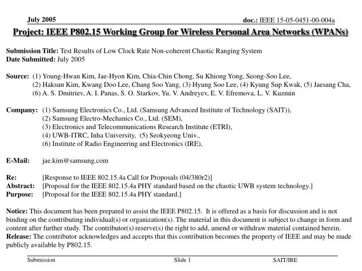
Project: IEEE P802.15 Working Group for Wireless Personal Area Networks (WPANs) Submission Title: Test Results of Low Clock Rate Non-coherent Chaotic Ranging System Date Submitted: July 2005 Source: (1) Young-Hwan Kim, Jae-Hyon Kim, Chia-Chin Chong, Su Khiong Yong, Seong-Soo Lee, (2) Haksun Kim, Kwang Doo Lee, Chang Soo Yang, (3) Hyung Soo Lee, (4) Kyung Sup Kwak, (5) Jaesang Cha, (6) A. S. Dmitriev, A. I. Panas, S. O. Starkov, Yu. V. Andreyev, E. V. Efremova, L. V. Kuzmin Company: (1) Samsung Electronics Co., Ltd. (Samsung Advanced Institute of Technology (SAIT)), (2) Samsung Electro-Mechanics Co., Ltd. (SEM), (3) Electronics and Telecommunications Research Institute (ETRI), (4) UWB-ITRC, Inha University, (5) Seokyeong Univ., (6) Institute of Radio Engineering and Electronics (IRE), E-Mail: jae.kim@samsung.com Re: [Response to IEEE 802.15.4a Call for Proposals (04/380r2)]Abstract: [Proposal for the IEEE 802.15.4a PHY standard based on the chaotic UWB systemtechnology.]Purpose: [Proposal for the IEEE 802.15.4a PHY standard.] Notice: This document has been prepared to assist the IEEE P802.15. It is offered as a basis for discussion and is not binding on the contributing individual(s) or organization(s). The material in this document is subject to change in form and content after further study. The contributor(s) reserve(s) the right to add, amend or withdraw material contained herein. Release: The contributor acknowledges and accepts that this contribution becomes the property of IEEE and may be made publicly available by P802.15. SAIT/IRE
Test Results of Low Clock Rate Non-coherent Chaotic Ranging System Presented by: Jae-Hyon Kim Samsung Advanced Institute of Technology (SAIT) Institute of Radio Engineering and Electronics (IRE) SAIT/IRE
Objective • To provide the real hardware test results of non-coherent ranging system based on chaotic signal • To show the low cost solution using low rate clock (2.500 MHz) for non-coherent ranging system • To show the low hardware complexity of chaotic source when it is implemented in CMOS SAIT/IRE
Chaotic Signal • Chaotic signal is flexible enough to accommodate to Burst PPM or Burst OOK non-coherent ranging system Chaotic PPM Option-I (Burst PPM) Impulse Chaotic Source (option) Chaotic OOK Burst OOK SAIT/IRE
Video Recording of Experiments SAIT/IRE
Direct Chaotic UWB System • No need Conventional UWB RF Devices • nano scale time synchronization • Up/Down Mixer , PLL Chaos Generator Microwave Amplifier Input PC signal Inverter 1 Digital Board Modulator and Switch Inverter 2 Output signal to PC Demodulator Low noiseamplifier SAIT/IRE
Low Clock Rate Ranging Method This ranging algorithm can be applied to a system that compare the reference clock and the received waveform or only by comparison of two different rate of clock waveform N1, N2, N3 – pulse numbers N1 Tx С1 Tx= (N3+0.5N2)/f1 – (N1+0.5N2)/f0 N2 С2 N3 distance S = 0.5*c*(Tx-0) t* * C3: Ref clock 0 – retranslation time t2 t3 t0 t1 delayed pulses(2.500 MHz) and reference pulses(2.5025 MHz) Operation time of counters C1,C2,C3. Delayed pulse Reference pulse SAIT/IRE
AD9833 Low Clock Rate • Implementation example of two synchronized clocks with 2.500 MHz and 2.5025 MHz rates 2.500 MHz CPLD Programmable Waveform Generator can be implemented by means of AD9833 chip (Analog Devices) 20 MHz Clock source 2.5025 MHz Programmable Waveform Generator Control unit (Digital Block ) SAIT/IRE
Target TRF TLF + RF cable TRF - Propagation delay through the RF cable - Propagation delay through the LF wire TLF Cable Experiment SAIT/IRE
Test Results of Cable Experiment Mean-Square Error <σ> = 1.3 ns SAIT/IRE
Wireless experiment Transceiver Target LF wire TRF TLF + TRF - Propagation delay through free space - Propagation delay through the LF wire TLF SAIT/IRE
Test Results of Wireless Experiment Error RMS = 0.6 ns (0.18 m) SAIT/IRE
Features of Chaotic UWB Technology • Low Power Consumption ( 10mW ) • Simplicity of Hardware Structure ( Low Cost Realization ) • Easy Synchronization ( Low Cost Realization ) • Not critical to antenna performance SAIT/IRE
CMOS IC (On Chip) BPF (Off Chip) Chaotic Generator (CMOS IC) • 5stage Ring Oscillator • Power Consumption:6.4mW(3.6mA, 1.8V) • Very Simple Architecture Without Inductors SAIT/IRE
200um 300um Chaotic Generator (CMOS IC) • Layout of the 5stage Ring Type Generator SAIT/IRE
Conclusion • Chaotic system is a low cost, low power solution for non-coherent communications and ranging system • Easy to synchronize and it is not critical to antenna performance • The simulation results against multipath will be provided soon. Note: Please refer to Appendix A and B for more information related to the ranging error estimation and the Chaotic source implementation in CMOS respectively. SAIT/IRE
Appendix ARanging Error Estimation SAIT/IRE
(Appendix A) Ranging (1) Error estimation concerning the generator frequency drift • Basic assumptions: • Two pulse sequences are generated, the first one is video pulses and • the second one is chaotic; • The generator has some frequency drift; • As two sequences have one origin, their frequency drifts are synchronized; • The frequency drift depends linearly on the time; • There is constant error in time estimation because of finite resolution of • the generator; MHz - frequency of the chaotic pulses sequence MHz - frequency of the video pulses sequence Error from the finite resolution ns SAIT/IRE
(Appendix A) Ranging (2) T1 – period of the video pulse sequence, T2 – period of the chaotic pulse sequence Synchronized drift: T2=T1(1+a), a=const. Periods are changed linearly (according to basic concepts); T1=T10+d1n, T2=T20+d2n, n – the number of pulses, d1, d2 – drifts of sequence periods For the time error estimation because of drift we have the formula Example of calculation: According to model: a~10-3; n~103 For drift D = 20 ppm, d1 = 2T1D×10-12 = 2*400×20×10-12 = 16×10-9 ns Then the error is = 8×10⁻⁶ ns SAIT/IRE
(Appendix A) Ranging (3) Dependence of the time and distance errors on the drift of the generator frequency SAIT/IRE
(Appendix A) Ranging (1)Derivation of drift error estimate Periods of the two sequences: T1=T10+d1n, T2=T20+d2n; Basic expressions for time estimation: n1T1 = + n2T2(1) with drift n1T10 = 0 + n2T20 (2) without drift The sequences are synchronized, then d2=d1+a; T1,T2 are arithmetical progressions, then in n1 and n2 steps (1) is Subtracting (2) from (3), we have the error For majority of distances (0-60 m): n1=n2+1, then SAIT/IRE
(Appendix A) Ranging (2)Derivation of drift The period of the sequence is T1n=T10+d1n If generator drift is D ppm (D pulses per million pulses), then for million original pulses there is (106-D) drifting pulses, so but 106T10 = (106-D)(T10 + dT10(106-D)/2) Hence, d 2DT10×10-12 SAIT/IRE
Contents • System Spec. • Frequency Plan • System Link Budget • Transmitter Block Design • Receiver Block Design SAIT/IRE
System Specification SAIT/IRE
Proposed Frequency Plan Band No. 4 207 MHz 111 MHz 1 2 3 3 4 5 GHz 3.25 3.5 3.75 4.25 4.5 4.75 Note: This plan has almost double margin to 4.9 GHz as compared to 3.1 GHz SAIT/IRE
IEEE802.15.4a System PHY Structure RF System Block MODEM System Block Wake-up Receiver MAC H/W DC Power Control Ranging Detection Chaotic RF Receiver Digital Demodulator Chaotic RF Transmitter Digital Modulator Control Logic & Resisters SAIT/IRE
E F G H D C B A Modem C A B H D E F G Chaotic Transceiver Block Diagram SAIT/IRE
System Link Budget & Sensitivity • 500MHz Bandwidth SAIT/IRE
Chaotic Transmitter • Performance of Transmitter Defend on Chaotic Signal Characteristics • Poor Isolation of Modulators Can limit a Dynamic Range of Chaotic signals SAIT/IRE
CMOS IC (On Chip) BPF (Off Chip) Chaotic Source (II) Chaotic Generator (I) • 5stage Ring Oscillator • Power Consumption:6.4mW(3.6mA, 1.8V) • Very Simple Architecture Without Inductors SAIT/IRE
Chaotic Source (II) Chaotic Generator (I) • Simulation Result • Chaotic Signal in Time Domain • Chaotic Signal in Frequency Domain SAIT/IRE
200um 300um Layout of Chaotic Source (II) Chaotic Generator (I) • Layout of the 5stage Ring Type Generator SAIT/IRE
Chaotic Source (III) Chaotic Generator (II) • Block Diagram of Advanced Chaotic Generator In_V Out_V • Power Consumption:4.5mW(2.5mA, 1.8V) • Chaotic Signal Generation by Mixing Pulse Signals • Very Stabile Chaotic Signal Generation SAIT/IRE
Out_V In_V Chaotic Source (III) Chaotic Generator (II) • Simulation Result • Chaotic Signal in Frequency Domain • Chaotic Signal in Time Domain • Chaotic Phase Portrait SAIT/IRE
Colpitts Chaotic Source (III) • Colpitts Chaotic Generator • Very Sensitive to the Current and Impedance • BPF acts on Chaotic Mode Resonator and Band Selection Filter SAIT/IRE
Power Amplifier • 3stage Cascode Power Amplifier • Gain: 35dB, P1dB: 10dBm • Power Consumption:14.4mW(8mA, 1.8V) • R-C Shunt Feedback to Improve Stability and Wideband Frequency SAIT/IRE
0 V 0.7 V 1.5V Varactor Tunable Piconet Filter • 3 Band(BW:500MHz) Tunable Interdigital Filter • Capacitance Varied by Voltage in Varactors • Due to the Parasitic of the Varactor, Implementation is Very Difficult SAIT/IRE
Chaotic Receiver • Non-Coherent Receiver • Direct Digital Communication in Air Using a Stream Chaotic Radio Pulses • Robustness against Internal System Noise • Design Goal: Low Cost and Low Power Consumption SAIT/IRE
Low Noise Amplifier • 4stage Low Noise Amplifier Functioning as BPF of 4 Poles • Gain: 48dB, P1dB: 9dBm, Noise Figure: 2.6dB • Power Consumption:19.8mW(11mA, 1.8V) • Due to the BPF Characteristics, Architecture of Receiver can be Simple • Due to the poor sensitivity of detector, it is required to get enough gain at the front end of receiver. SAIT/IRE
Low Noise Amplifier • Simulation Result Noise Figure (dB) Gain Out Power SAIT/IRE
Envelope Detector • Signal Waveforms SAIT/IRE
Conclusion Remarks • Non-Coherent CMOS Transceiver IC Design . 3 Type Chaotic Generator . Piconet Band Pass Filter . Power Amplifier . Low Noise Amplifier . Envelope Detector • We have Proposed the Power Consumption and Chip Size of the Chaotic UWB Transceiver • The Feasibility of Chaotic CMOS Implementation was Proved by Simulation • We are going to test CMOS Chip of Chaotic UWB Transceiver from now on SAIT/IRE