Download
1 / 43
430 likes | 562 Views
European Ultra-light to Heavy-lift Stratospheric Balloons in the Polar Regions. Svalbard - Norway & Baia Terra Nova - Antarctica. The Idea…. Develop a program in the northern polar region for Long Duration Ballooning – take the project to Antarctica

E N D
EuropeanUltra-light to Heavy-lift Stratospheric Balloons in the Polar Regions Svalbard - Norway & Baia Terra Nova - Antarctica
The Idea… • Develop a program in the northern polar region for Long Duration Ballooning – take the project to Antarctica • Introduce science and technological payloads… small platforms < 25kg • Bring students into the program
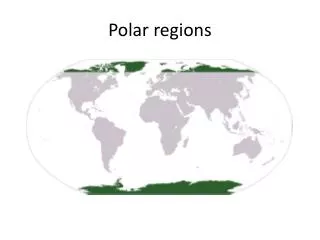
Location, location, location! • Over-fly minimal population yet retain a recovery zone. This is a given for Antarctica…but rare in the north. • Impact area that would cause the minimal environmental damage. Impact and recovery in the tundra leaves scars. The Greenland Ice Sheet offers a perfect target.
Intheory, a stratospheric balloon launched from Svalbard, Norway should be carried around the polar region and return back over Svalbard…continue on, and be terminated over Greenland.
THE PERFECT CIRCLE…ALMOST! First complete circumpolar trajectory - North 17 DAY FLIGHT Impact – July 1st, 2006 Svalbard Greenland Launched - June 14th, 2006
ALTITUDE vs TIME 34km Ballast Drop
Stratospheric Winds… • Through Satellite Derived Wind Data we know that the circulation pattern should be “set-up” to support a circumpolar trajectory by the first week of June. • A model of the wind predictions was constructed…Cardillo/Musso – ISTI/CNR The model and the actual flight path coincide.
The Payload • Telemetry – IRIDIUM, ARGOS (Elta) • Power supply – SOLAR • Science – Magnetometer (INGV)… X-RAY Detector ( Student Experiment - University of Tromso, NO) TELEMETRY & MAGNETOMETER BUILT BY INGV (Rome)…Gianni Romeo
features Installing scientific instruments on a pathfinder offers the opportunity of exploring Polar Regions at an affordable cost. PEGASO hosts a 3-axis flux-gate magnetometer and is a complete flying geomagnetic observatory for studying geomagnetic crustal anomalies at continental scale as well as stratospheric circulation. PEGASO offers: • Solar power • Local data storage • Bi-directional link to the ground station • Ballasting and termination control
Cylindrical solar array Solar cells are manufactured by depositing multiple layers of silicon alloy materials onto a thin stainless steel substrate The array is composed by very long single cells going trough the whole cylinder surface. During the flight they are lit always in the same way, for a good performance. Illumination over the plane representation of the cylindrical array System symmetry and flying area guarantee a constant illumination during the flight. This simplifies the charge control (no MPPT)
Solar array Solar cells are manufactured by depositing multiple layers of silicon alloy materials onto a thin stainless steel substrate in a patented roll-to-roll production process. The cell assembly is laminated (sealed) in flexible and durable weather resistant polymers that provide long life, high reliability. Bypass diodes are connected across each cell to produce shadow tolerance performance. The resulting solar cells are processed and connected in series to provide the required voltage. Eleven cells are connected in series to produce the required voltage for 12 volt battery charging.
Communication: WhyIRIDIUM ? Low cost and good data rate where mandatory in this project. Point to point telemetry is difficult in polar areas, requiring too many ground stations; traditional satellite low-cost telemetry, ARGOS, is low data rate and is downlink only. Iridium is more expensive, more heavy and more complex (not more than an usual telephonic AT modem) but offers a bidiretional telemetry a good coverage in polar areas and a reasonable data rate
Iridium constellation • 66 satellites (6 orbiting spares) a 780 km • 100 minutes revolution period • Communication to ground users 1616..1625 MHz • satellite-satellite communication 23.18-23.38 GHZ • satellite-ground communication 19.4..19.2 GHz • Ground-satellite communication 29.1-29.3 GHz • Digital channel speed 2400 bps
Phone used in PEGASO Ordinary Iridium phones offer both acoustic and data communication (for just 1.5 Euro/min). The complexity of the ground station is shown below: just a notebook and an Iridium phone with a data kit.
How to build your own telemetry system Setting up a working Iridium data link is not much more difficult than building an ordinary point-to-point connection: it is just necessary to take in account the transmission delay and operate the right choice of packets length (time is money). 23 GHz 1.6 GHz 1.6 GHz rs232 rs232 satellites Data computer Data computer kit kit
PEGASO block diagram IRIDIUM data kit IRIDIUM phone rs232 antenna RCM2000 main processor rs232 Main processor monitor Level adapter rs232 Digital I/O rs232 on-off phone GPS receiver antenna adc board Vessel temperature Arm temperature scientific adc 8 channels igniter driver Solar array Panels temperature To and from igniters Panels voltage Panels current Battery voltage 3 channels magnetometer Magnetometer head power supply Charge controller Low battery switch Data monitor battery
PEGASO layout 10 cm GPS Antenna IRIDUM Antenna U0 Mechanical assembly Temperature sensor Boards description U0 : IRIDIUM Telephone U1 : CPU and GPS Receiver U2.1: Flux Gate (Ch1) U2.2: Flux Gate (Ch2) U2.3: Flux Gate (Ch3) U3 : ADC board U4 : power supply U5 : charge controller U6 : igniters driver and tester U1 U2.1 70 cm U2.2 Boards U2.3 U3 U4 U5 U6 Battery Testing connector Panels connector Flux Gate Magn. conn. Ballast / Release connector
Ground station at INGV • Communication with 4 balloons • Data available via web server • Status via SMS • Workstations via VPN Linux PC LAN Web server modem GSM modem Local storage
Ballast releasing Ballast tube may be remotely operated during the flight. Pictures on the right show the effect of the releasing on the altitude.
Flight System • Balloon – AeroStar, SF3-0.327-.6/0-TA 9258 m³ • Parachute – 40 kg rating • Terminate – Redundant squibs • ARGOS Transmitter – On balloon used for tracking during flight and termination • Radar Reflectors – 2 • Meets International Rules of the Air
Ultra-Light Payloads • Great Vehicle for technological testing • Great Vehicle for science component testing • Low cost • Easy to transport equipment • Launch from nearly any location – airport, sports field, roadway, etc. • Complete Recovery…nothing left behind
Students and Ultra-Lite payloads • Affordable for most organizations • Hands on experience • Involvement in all aspects of the program • Stepping stone to future involvement in ballooning.
Baia Terra Nova - Antarctica • Ultra-Lite Balloon launches • Known trajectory pattern • Recovery options • January 2006 launched the first PEGASO experiment from BTN.
Ultra-Light systems help to teach students the various aspects of ballooning • LDB with ultra-light systems is a cost efficient way to reach near space for testing purposes. • Ultra-Light Payloads lead to Heavy-Lift Payloads... • Like the forthcoming OLIMPO and BOOMERanG, to be flown from Svalbards next year
(http://oberon.roma1.infn.it/olimpo) OLIMPO An arcmin-resolution survey of the sky at mm and sub-mm wavelengths Silvia Masi Dipartimento di Fisica La Sapienza, Roma and the OLIMPO team
CMB anisotropy SZ clusters Galaxies 150 GHz 220 GHz 340 GHz 540 GHz 30’ mm-wave sky vs OLIMPO arrays
OLIMPO observations of a SZ Cluster • Simulated observation of a SZ cluster at 2 mm with the Olimpo array. • The large scale signals are CMB anisotropy. • The cluster is the dark spot evident in the middle of the figure. • Parameters of this observation: scans at 1o/s, amplitude of the scans 3op-p, detector noise 150 mK s1/2, 1/f knee = 0.1 Hz, total observing time = 4 hours, comptonization parameter for the cluster y=10-4. 3o 3o
The uniqueness of OLIMPO • OLIMPO measures in 4 frequency bands simultaneously. These bands optimally sample the spectrum of the SZ effect. • This allows us to clean the signal from any dust and CMB contamination, and even to measure Te by means of the relativistic corrections.
BOOMERanG 28/Dec/1998
BOOMERanG 06/Jan/2003
B98 results: First resolved map of the CMB at sub-horizon scales • Flatness of the Universe • See de Bernardis et al. 2000, Netterfield et al. 2002, Ruhl et al. 2003 • B03 results: detection of CMB polarization (E-modes) • See Masi et al. 2005, Montroy et al. 2005, Piacentini et al 2005
BOOMERanG-FG • We plan to re-fly B03 with an upgraded forcal plane, to go after foreground cirrus dust polarization. • This information is essential for all the planned B-modes experiments (e.g. BICEP, Dome-C etc.) and is very difficult to measure from ground. • The BOOMERanG optics can host an array of >100 PSB at >350 GHz.
BOOMERanG-03 140 GHz PSB 240 GHz 340 GHz BOOMERanG-FG 140 GHz PSB 340 GHz PSB Frequency range complementary to PILOT (higher f. J.F. Bernard, Toulouse)
ISM is everywhere ! With Boom-FG we will study the polarization properties in the clean region in the northern hemisphere North 270o 270o south B03 180o 0o 180o 90o 90o Dust brightness @ 3000 GHz (log scale)
EuropeanUltra-light to Heavy-lift Stratospheric Balloons in the Polar Regions In summary, a Svalbard-based facility provides a unique opportunity for long duration flights, to be used for didactic/outreach light experiments, as well as for heavy science payloads. The same know-how will be used for launches from Antarctica.