Download
1 / 14
220 likes | 1.08k Views
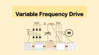
Variable Frequency Drives Bypass Options. VFD Bypass Operation. Two Contactor Bypass. Power Supply. SED2 Drive. Mechanically Interlocked. Drive Output Contactor. Bypass Contactor. Motor. VFD Bypass Operation. Three Contactor Bypass. Power Supply. Optional Input Contactor. SED2

E N D
VFD Bypass Operation Two Contactor Bypass Power Supply SED2 Drive Mechanically Interlocked Drive OutputContactor Bypass Contactor Motor
VFD Bypass Operation Three Contactor Bypass Power Supply OptionalInputContactor SED2 Drive Mechanically Interlocked Drive OutputContactor Bypass Contactor Motor Optional “3rd” drive input contactor electrically isolates the VFD
Bypass Types – Conventional and Electronic • Conventional bypass – uses hard-wired electrical components for mechanical bypass control • Switches • Fuses • Relays • Electronic bypass – electronic logic control with simple keypad • Reduced wiring and mechanical components • Improved system reliability • Additional logic features standard • Interlocked Start • 2 Safety circuits • Smoke Purge logic Conventional Bypass Electronic Bypass
SED2 Conventional Bypass • VFD and Bypass cabinet mounted on common back plate • Conventional electromechanical control • Indicating lights, selector switches, relays • All voltages and HP ratings • Configurations available: • Disconnect (fused on non- fused) • NEMA 1 cabinet • 2 or 3 contactor control • manual/auto bypass selection standard • line/load reactor option • Damper end-switch logic option
Conventional Bypass Components Protectivecover Gland Plate Conduit Connector Mounting Back Plate Bypass ON Indicator Light Drive /Off / Bypass Selector Line Disconnect Drive Test Selector (3 contactor only)
Conventional Bypass Components Line reactor (optional) Controltransformer Input contactor (optional) Controlrelays Power fuses (optional) Output contactor Line disconnect Bypass contactor Motoroverloadrelay Field wiring terminals
For more info, see the Bypass menu on this CD Conventional Bypass Power Range A-F denotes VFD frame size
Electronic Bypass Features • Easy-touch keypad with status display • Common remote start/stop • Auto bypass • Essential service mode • Interlock start logic • Disconnect options • Disconnect • Fused Disconnect • Circuit Breaker • Two and three contactor models • 6 digital inputs and 6 digital outputs • Optional line or load reactor
Electronic Bypass Components Electroniccontrolboard Input contactor (optional) Fieldwiringterminals Line reactor (optional) Power fuses (optional) Controltransformer Line disconnect Outputcontactor Bypass contactor Motoroverloadrelay
Electronic Bypass Keypad • Easy-touch electronic keypad displays status and operating configuration • Indicates current status with 14 LEDs • Built -in logic reduces wiring and ensures safe operation
Electronic Bypass Keypad Features Indicates that input contactor is closed and drive has power. Indicates input contactor is closed when on, close pending when flashing. Toggling this button opens / closes the input contactor. Enables hand bypass mode. Enable remote bypass. Bypass light w/ flash. Contactor closes and light comes on when Remote Start input closes. Enable closes both drive input and output contactors. Essential service light flashes when this feature is activated. Auto Bypass light flashes when this feature is activated. Disconnect the motor whether in drive or bypass mode. Indicates that one of the safety inputs is open. Indicates that either the overload input has closed or that the thermal overload has tripped. Indicates present operational state of interlocked start logic.
For more info, see the Bypass menu on this CD Electronic Bypass Power Range A-F denotes VFD frame size
Siemens SED2 VFD Advantages • Low harmonics design • Small enclosure size • Many standard features • Reduces operating cost • Low power losses/high efficiency • Minimal effect on customer power • Wide power range – from ½ to 125 HP