Download
1 / 1
10 likes | 112 Views
Investigation of Wireless Power Transfer in Through-Wall Applications. Matt Hoang, Young- Sik Seo , Zachariah Hughes, Deena Isom , Minh Nguyen, Smitha Rao , and J.-C. Chiao NSF REU: Sensors and Applications, The University of Texas at Arlington, Arlington, Texas 76019. Abstract

E N D
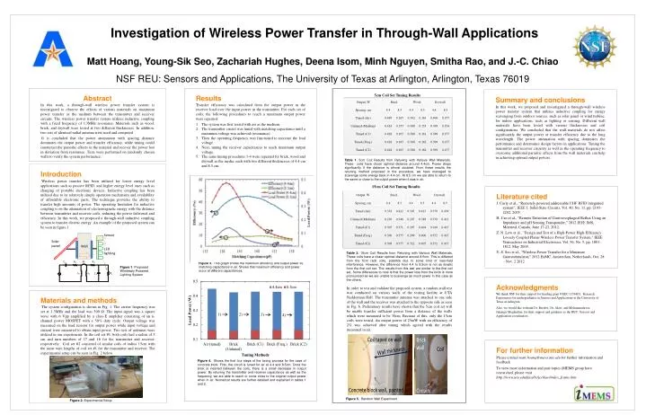
Investigation of Wireless Power Transfer in Through-Wall Applications Matt Hoang, Young-SikSeo, Zachariah Hughes, Deena Isom, Minh Nguyen, SmithaRao, and J.-C. Chiao NSF REU: Sensors and Applications, The University of Texas at Arlington, Arlington, Texas 76019 Abstract In this work, a through-wall wireless power transfer system is investigated to observe the effects of various materials on maximum power transfer as the medium between the transmitter and receiver circuits. The wireless power transfer system utilizes inductive coupling with a fixed frequency of 1.3MHz resonance. Materials such as wood, brick, and drywall were tested at two different thicknesses. In addition, two sets of identical radial antenna were used and compared. It is concluded that the power attenuation with spacing distance dominates the output power and transfer efficiency, while tuning could counteract the parasitic effects in the material and recover the power lost in deviation from resonance. Tests were performed on randomly chosen walls to verify the system performance. Results Transfer efficiency was calculated from the output power in the receiver load over the input power in the transmitter. For each set of coils, the following procedures to reach a maximum output power were repeated: The system was first tested with air as the medium. The transmitter circuit was tuned with matching capacitance until a maximum voltage was achieved (resonance). Then the operating frequency was fine-tuned to increase the load voltage Next, tuning the receiver capacitances to reach maximum output voltage. The same tuning procedures 1-4 were repeated for brick, wood and drywall as the media, each with two different thicknesses of 4.4 cm and 8.5 cm. Summary and conclusions In this work, we proposed and investigated a through-wall wireless power transfer system that utilizes inductive coupling for energy scavenging from outdoor sources, such as solar panel or wind turbine, for indoor applications, such as lighting or sensing. Different wall materials have been tested with various thicknesses and coil configurations. We concluded that the wall materials do not affect significantly the output power or transfer efficiency due to the long wavelength. The power attenuation with spacing dominates the performance and determines design factors in applications. Tuning the transmitter and receiver circuitry as well as the operating frequency to overcome additional parasitic effects from the wall materials can help in achieving optimal output powers. 5cm Coil Set Tuning Results Table 1. 5cm Coil Results from Retuning with Various Wall Materials. These coils have closer optimal distance around 4.4cm. Power drops significantly if the distance is almost doubled. From these results the retuning method proposed in the procedure, we have managed to scavenge some energy back in 4.4 cm. At 8.5 cm we are able to return to the same or close to the output power when it was in air. Introduction Wireless power transfer has been utilized for lower energy level applications such as passive RFID, and higher energy level ones such as charging of portable electronic devices. Inductive coupling has been utilized due to its relatively simple operation mechanism and availability of affordable electronic parts. The technique provides the ability to transfer high amounts of power. The operating limitation for inductive coupling is on the attenuation of electromagnetic energy with the distance between transmitter and receiver coils, reducing the power delivered and efficiency.In this work, we proposed a through-wall inductive coupling system to transfer electric energy. An example of the proposed system can be seen in figure 1. 15cm Coil Set Tuning Results Literature cited J. Curty et al., “Remotely powered addressable UHF RFID integrated system”, IEEE J. Solid-State Circuits, Vol. 40, No. 11, pp. 2193-2202, 2005. H. Cao et al., “Remote Detection of Gastroesophageal Reflux Using an Impedance and pH Sensing Transponder,” 2012 IEEE IMS, Montreal, Canada, June 17-22, 2012. Z. N. Low et al., "Design and Test of a High-Power High-Efficiency Loosely Coupled Planar Wireless Power Transfer System," IEEE Transactions on Industrial Electronics, Vol. 56, No. 5, pp. 1801-1812, May 2009. Y.-S. Seo et al., “Wireless Power Transfer for a Miniature Gastrostimulator,” 2012 EuMC, Amsterdam, Netherlands, Oct. 28 – Nov. 2 2012. Table 2. 15cm Coil Results from Retuning with Various Wall Materials. These coils have a closer optimal distance around 8.5cm. This is different from the 5cm radii coils, possible due to some kind of near-field interference. However, the difference from 4.4 to 8.5cm is not as drastic from the first coil set. The results from this test are similar to the first coil set. Some differences to note is that the power loss from the brick is more pronounced as we are unable to scavenge as much power in this case as the others. Figure 3. This graph shows the maximum efficiency and output power vs. matching capacitance in air. Shows that maximum efficiency and power occur at different capacitances. Figure 1. Proposed Wirelessly Powered Lighting System Acknowledgments We thank NSF for their support for funding grant # EEC-1156801, Research Experiences for undergraduates in Sensors and Applications at the University of Texas at Arlington. Also, we would like to thank Dr. Bredow, Dr. Alavi, and Mohammadreza Jahangir Moghadam for their support and guidance as the REU: Sensors and Application coordinators. In order to test and validate the proposed system, a random wall test was conducted on various walls of the testing facility at UTA Nedderman Hall. The transmitter antenna was attached to one side of the wall and the receiver was attached to the opposite side as seen in Fig. 6. Preliminary results have shown that the 5cm coil set will be unable transfer sufficient power from a distance of the walls which were measured to be 30cm. Because of this, only the 15cm coils were tested. An output power of 25mW with an efficiency of 2% was achieved after tuning which agreed with the results measured in air. Materials and methods The system configuration is shown in Fig. 1. The carrier frequency was set at 1.3MHz and the load was 500 Ω. The input signal was a square wave with 6 Vpp amplified by a class-E amplifier consisting of an n-channel power MOSFET with a 50% duty cycle. Output voltage was measured on the load resistor for output power while input voltage and current were measured to obtain input power. Two sets of antennas were utilized in our experiments. In the coil set #1, both coils had a radius of 5 cm and turn numbers of 17 and 16 for the transmitter and receiver, respectively. Coil set #2 consisted of similar coils of radius 15cm with the same wire lengths of coil set #1 for the transmitter and receiver. The experimental setup can be seen in Fig. 2 below. For further information Please contact matt.hoang@mavs.uta.edu for further information and feedback. To view more information and past topics iMEMS group have researched, please visit http://www.uta.edu/faculty/jcchiao/index_frame.htm Figure 4. Shows the first four steps of the tuning process for the case of concrete brick. First, the circuit is tuned for air at 4.4 and 8.5cm. Once the brick is inserted between the coils, there is a small decrease in output power. By retuning the transmitter and receiver capacitance as well as the frequency, we are able to reach or come close to the original output power when in air. Numerical results are further detailed and explained in tables 1 and 2. Figure 5. Random Wall Experiment Figure 2. Experimental Setup