Download
1 / 4
70 likes | 230 Views
Signal Fading Destructive interference due to multiple reflective paths of varying distances. This is a rare and transient phenomena, but it happens.

E N D
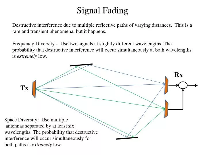
Signal Fading Destructive interference due to multiple reflective paths of varying distances. This is a rare and transient phenomena, but it happens. Frequency Diversity - Use two signals at slightly different wavelengths. The probability that destructive interference will occur simultaneously at both wavelengths is extremely low. Rx Tx Space Diversity: Use multiple antennas separated by at least six wavelengths. The probability that destructive interference will occur simultaneously for both paths is extremely low.
Additional Losses in Multi-Link Systems Rx1 GT GR . . . LS Rx LbR (Branching) LfR (Feeder) LF LfT (Feeder) RxN EIRP = P1 + GT - LbT - LfT LbT(Branching) Pr = EIRP – LS + GR - LF - LbR - LfR PN P1 . . . Since Fading is a transient phenomena, we usually provide a Fade Margin to account for LF in a statistical sense, e.g., 95%. TxN Tx1
System Gain GSYS,i(dB) = PT,i(dBw) – PR,i(dBw) = PT,i - ( PT,i – LbT – LfT + GT – LS – FM + GR – LfR – LbR) = LbT + LfT - GT + LS + FM - GR + LfR + LbR Using the convention we have adopted for use of the terms “Gain” and “Loss”, it would be more appropriate to call the above “Transmission Loss”. System Threshold System threshold is the input power required to achieve a specified S/N or C/N or EB/N0 Effective noise power at the Receiver input is N0B or kTRB, where TR is the Receiver Noise Temperature = 290(NRR-1). For a specified S/NREQ, PR > S/NREQ(kTRB) (not dB)
G/T For Digital systems, we are interested in achieving a specified EB/N0 , therefore PR > S/NREQ(kTRB) = {(EB/N0)(fB/B)}(kTRB) = (EB/N0)fBkTR Neglecting Branching, feeder, and fading losses, the received power is PR = (EIRP/LS)(GR) > (EB/N0)fBkTR Rewriting, (EIRP/LS)(GR /TR)/(fBk) > (EB/N0)REQ Note that the term (GR /TR) captures the two important parameters of the receiving system in one number. This number, G/T, is usually published to characterize receiving systems rather than giving the two values separately. The above relation , expressed in dB is therefore: (EB/N0)REQ < EB/N0 = EIRP(dBw) - LS (dB) + G/T(dB) – k(dB) - fB (dB) Note that eq. 17-26 in the text is totally wrong.